background image

                                                                                                                                       Twinspeedy / Sailspeedy


Sailspeedy / Twinspeedy instructions


Fuselage 


The  V-tail  servos  are  mounted  at  the  tail  end  of  the  fuselage, 
and have to be  extended to a length  of 65 cm to reach the RC 
system receiver, which is housed under the canopy at the front. 
Please  read  the  instructions  supplied  by  your  RC  system  and 
servo  manufacturer  regarding  extension  leads,  as  suppressors 
may be required. 
Test the servos to ensure that they work correctly after they are 
fitted with the extension leads. Wrap clear tape round the servo 
leads  for  a  distance  of  about  8  cm  to  protect  them  from  the 
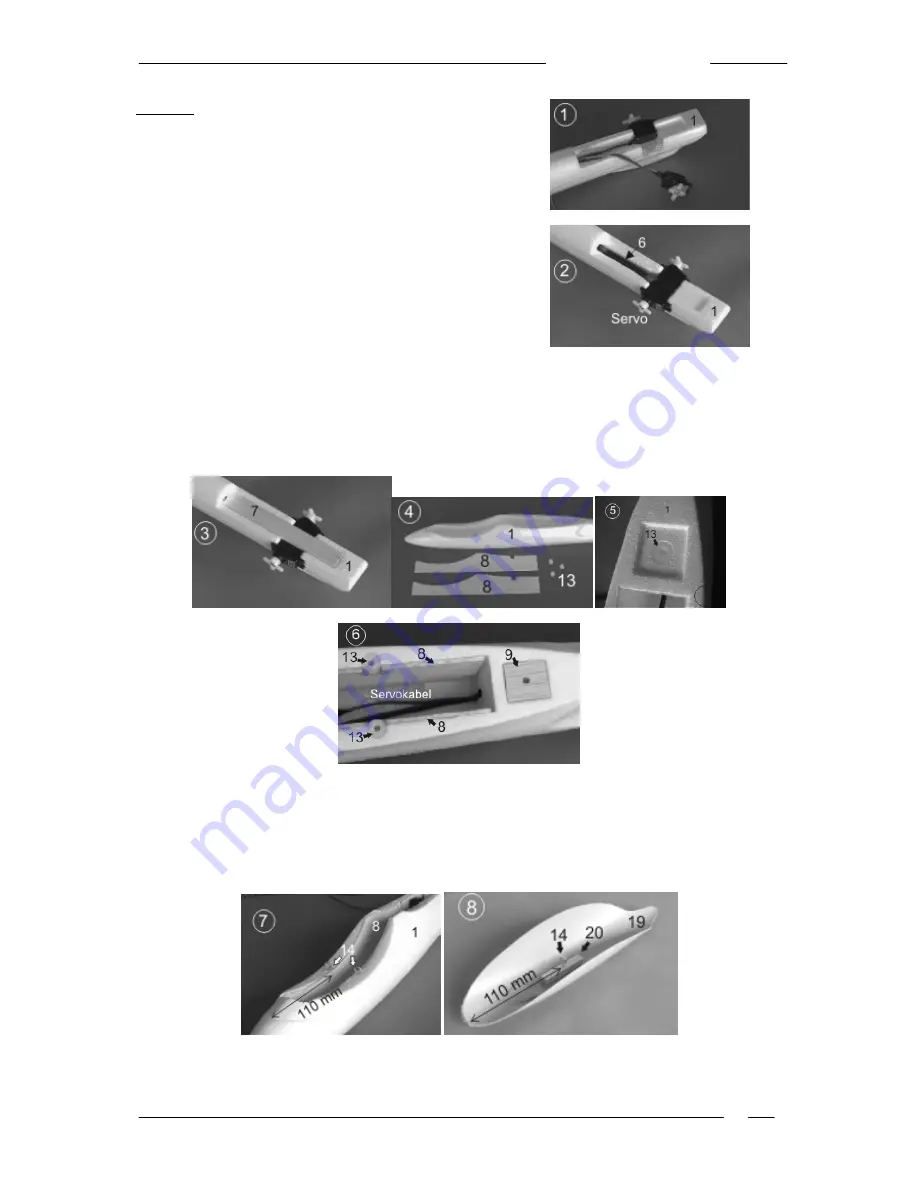
epoxy. Glue the two servos in the tail of the fuselage (1), run the 
leads  through  the  hole  in  the  fuselage  (1)  and  allow  them  to 
hang down (Fig. 1). 
The  next  stage  is  to  epoxy  the  carbon  fibre  tube  (6)  in  the 
fuselage (1) to stiffen and strengthen it. 


Slip the carbon fibre tube (6) into the fuselage (1) from the canopy end and position it just short of the 
servos  at  the  tail  end;  the  servo  leads  should  be  below  the  carbon  fibre  tube  (6)  (Fig.  2).  Glue  the 
balsa plate (7) in the recess at the tail of the fuselage (1) to stiffen it. It should fit over the two servos 
and the carbon fibre tube (6) (Fig. 3). 
Run the servo leads forward into the cabin area (Fig. 6). Seal the underside of the fuselage by gluing 
the balsa strip (12) in the channel; it should end flush with the outside skin of the fuselage. 


Glue  the  sheet  balsa  doublers  (8)  in  the  front  part  of  the  fuselage  (1)  on  both  sides  of  the  cockpit 
recess (Figs. 4 + 6). 
Three  threaded  nylon  sleeves  (13)  have  to  be  glued  in  the  fuselage  (1)  to  accept  the  wing  retaining 
screws: one on each side of the fuselage (1), where they are attached to the balsa doublers (8), and 
the third  in the circular recess at the rear  of the  wing saddle (Fig. 5). The  balsa reinforcement (9) is 
then glued on top of the third sleeve (13) (Fig. 6). 


The  two  ring-screws  (14)  can  now  be  glued  between  the  sides  of  the  fuselage  (1)  and  the  balsa 
doublers (8): press the ring-screws (14) into the fuselage, then enlarge the holes and epoxy the ring-
screws  securely  to  parts  (1  +  8)  (Fig.  7).  These  ring-screws  are  used  to  attach  a  rubber  band  (22) 

Summary of Contents for Twinspeedy

Page 1: ...ability for damage or injury caused during construction or operation of this model Flying this model successfully requires a basic knowledge of model flight If you are a beginner please ask an experienced model pilot to help you during the initial stages of learning to fly Use 5 minute epoxy for all joints Extra items required to complete the model 1 RC radio control system with V tail mixer 4 9 g...

Page 2: ...tail end the servo leads should be below the carbon fibre tube 6 Fig 2 Glue the balsa plate 7 in the recess at the tail of the fuselage 1 to stiffen it It should fit over the two servos and the carbon fibre tube 6 Fig 3 Run the servo leads forward into the cabin area Fig 6 Seal the underside of the fuselage by gluing the balsa strip 12 in the channel it should end flush with the outside skin of th...

Page 3: ... the fixed and moving panels Epoxy the two V tail panels 2 3 together and glue the balsa stiffener 10 in the recess on the underside Fig 10 The next step is to glue the V tail assembly to the tail end of the fuselage Cut a slot in the V tail control surfaces 2 3 to accept the GRP horns 16 Fig 11 the horns 16 must be parallel to the servo output arms Fig 13 Roughen the joint surface of the horns wi...

Page 4: ...the wing Fig 16 They act as reinforcements for the wing screws used to secure the wing 4 to the fuselage 1 Twinspeedy The wing of the Twinspeedy features two moulded in fairings into which the electric motors are glued from the underside Before installing the motors the power supply leads must be soldered to the terminals If the motors do not feature factory fitted suppressors three ceramic capaci...

Page 5: ...int under the wing roots on two fingertips When correctly balanced the model will hang level with the nose slightly down Parts list No Part Material No off Size 1 Fuselage High density foam 1 Ready made 2 V tail panel right High density foam 1 Ready made 3 V tail panel left High density foam 1 Ready made 4 Wing High density foam 1 Ready made 5 Wing spar Carbon fibre tube 1 748 x 4 9 Ø mm 6 Fuselag...

Reviews: