background image

www.aeroplusrc.com


service@aeroplusrc.com


AeroPlus


RC


Copyright


2013


©


All


Rights


Reserved


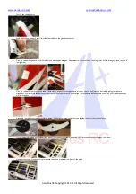
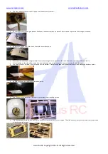
Using


the


pushrod


supplied


screw


ball


joints


onto


each


end.


The


correct


length


will


leave


the


aileron


lined


up


to


the


inner


part


still


attached


to


the


wing.


Using


supplied


bolts


attach


the


pushrod


at


both


ends.


Check


to


see


you


have


sufficient


movement


of


the


aileron.


If


not


adjust.


Carry


out


the


same


procedure


on


the


other


wing.


Gas


Engine


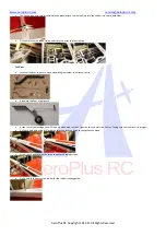
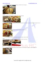
From


the


template


that


came


with


the


engine,


using


the


cross


axis


on


the


engine


box


mark


the


mounting


holes.


Check


the


diameter


of


the


required


bolts


and


drill


accordingly.


Mount


the


engine


with


the


stand


offs


to


the


bulkhead.


Remember


to


use


large


washers


on


the


inside


to


spread


the


load


and


use


plenty


of


nutlock.


Exhaust


options.


Depending


on


the


engine


many


exhaust


options


are


available.


Standard


muffler,


Pitts


Exhaust


of


canister


with


header.


If


using


a


canister


a


bracket


is


already


inside


the


model.


Using


silicon


tubing


it


will


hold


the


end


of


the


canister.


Summary of Contents for L-G030008

Page 1: ...s 4400g 5000g Glow 91 1 20 2C 1 10 1 40 4C Gasoline 26 35cc gas DLE 30 35RA MLD35 JC30Evo Electric 6 8S Lipo Radio 4CH 5 6 servos Description Covering Material Chinakote Carbon Fibre Wing tube Aluminu...

Page 2: ...o you some of the covering may have wrinkles We highly recommend that you take time to re seal all covering edges with an iron and to use a heat gun to remove any wrinkles and re tighten the covering...

Page 3: ...ing 2 spanners Place a collet on the axle followed by the wheel then another collet on the outside as per below diagram Do not tighten up the collets yet as the wheel needs to be fitted an equal dista...

Page 4: ...rns that goes inside the elevator needs to be roughed up with sandpaper This allows a better glue joint Glue the horns in place with epoxy glue Put a bolt through the ball joint hole to make sure that...

Page 5: ...holes Re fit the elevator servo and secure it in with servo screws Centre the servo using your TX and fit a servo arm Use either an aftermarket arm or attach the arms that were supplied to a servo he...

Page 6: ...th epoxy wipe off excess glue while it is wet Use the ball joint and bolt while gluing to maintain alignment While still movable measure that the same amount pushes out each side Care needs to be take...

Page 7: ...Gear Locate all parts as in picture when assembling remember to nutlock all parts Assemble the Gear as per photo At the rear of the fuselage you will find a ply wood area lay the CF gear on this and m...

Page 8: ...orns are glued in place Use either a soldering iron or a sharp knife Using sand paper rough the area that will be glued into the aileron Glue both horns in with epoxy glue use a bolt through the horns...

Page 9: ...dure on the other wing Gas Engine From the template that came with the engine using the cross axis on the engine box mark the mounting holes Check the diameter of the required bolts and drill accordin...

Page 10: ...n get out of the cowl The ration is usually 3 time out to 1 in Fit the ignition on the side of the motor box Use Velcro and also a strap to ensure it does not come off with vibration The cowl is fixed...

Page 11: ...u may need to use the supplied round plywood spacers to achieve the correct length for the motor Mount the ESC in airflow on the side of the electric motor mount using a velco strap With the removal o...

Page 12: ...nential Elevator 15 20 deg 15 20 35 45 deg 45 60 Ailerons 15 20 deg 15 20 35 45 deg 45 60 Rudder 25 30 deg 15 20 35 45 deg 45 60 For test flights always use low rates remember that and exponential is...

Reviews: