18
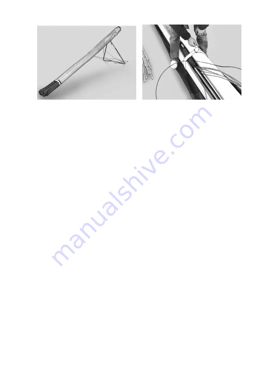
Figure 31
Figure 32
12.12. Secure the sail with the Velcro sail ties. The first Velcro tie is installed by passing it over the top of the keel
tube just near the Crossbar-LE tube junctions, and then installing it around the glider leading edges.
12.13. Place the bag with battens in the front part of the wing between Mylar pockets along the keel, put the nose
cone under the front Velcro tie. Secure the sail with remaining sail Velcro ties
(Fig. 31).
12.14. Install the glider bag. Flip the glider over onto the ground. Detach the basebar and place it between the
leading edges in the bag provided.
12.15. Fold up the control frame and install the control frame protection bag, lay it down against the keel. Undo the
Velcro, which was done first, reach it out to free the keel tube and install it again around both leading edges with the
control bar inside. Bring all wires forward along tubes and place downtubes between Mylar pockets
(Fig. 32).
12.16. Disconnect the outer part of the tail section from the centre tail section.
Place the tail between leading edges with its wide end towards the keel tube end and place winglets next to the
basebar.
12.17. Zip up the glider bag.
The glider is ready for transportation.
13. REMOVING THE SAIL FROM THE AIRFRAME AND RE-INSTALLING
Many maintenance and repair procedures will require the removal of the sail from the frame. Please follow these
instructions when removing and reinstalling the sail. Please read all the instructions for each operation before
beginning.
13.1. SAIL REMOVAL
You will need an unobstructed area 2 m by 10 m (6x30 ft). Make sure the surface is clean. If it is abrasive, you should
either put down a protective tarp or be extremely careful not to scrape your sail.
13.1.1. Lay the glider on its back, unzip and remove the glider bag. Untie the velcro ties, remove the basebar,
winglets, tail, battens and put them aside. Remove the control bar protection bag.
13.1.2. Spread the wings slightly. Remove central battens from the sail. Dismount the sail from the front leading edge
by unscrewing the sail mount screw. Undo the sail mount webbing Velcro and remove the sail mount webbing from
the plastic end at the rear leading edge.
13.1.3. Put a chair or other similar height support under the nose of the glider.
13.1.4. Remove the screw from the keel pocket webbing at the rear part of the keel tube. Detach the rear cables from
the keel tube.
13.1.5. Dismount the control bar apex assembly from the keel tube. Unbolt the hang point tower with a spreader bar
and a hang loop from the keel tube and slide it forward, along the keel.
Summary of Contents for Combat-12.4-GT
Page 2: ...2 ...
Page 29: ...Combat GT 12 4 12 7 13 5 ...
Page 30: ......
Page 31: ......
Page 32: ......
Page 33: ......
Page 34: ...CBT10 12 023 000 AD CBT10 12 023 000 AD ...
Page 35: ......
Page 37: ......
Page 38: ......
Page 39: ......
Page 40: ......
Page 41: ......
Page 42: ......
Page 44: ......
Page 51: ......
Page 52: ......
Page 53: ......
Page 54: ...CBT 200 000 AD ...
Page 55: ...CBT 200 000 AD ...
Page 56: ...CBT 200 000 AD ...
Page 57: ...CBT2 220 000 AD ...
Page 59: ...Combat GT 13 5 STL 263 000 ...


