background image

Summary of Contents for Combat-12.4-GT

Page 1: ... GT Combat 12 4 Combat 12 7 Combat 13 5 OWNER SERVICE MANUAL Manufactured by AEROS Ltd Tel 380 44 4554120 Post Volynskaya St 5 Fax 380 44 4554116 Kiev 03061 E mail INFO AEROS COM UA Ukraine http www aeros com ua April 2021 ...

Page 2: ...2 ...

Page 3: ...edure 12 6 Laying the glider down flat 14 7 Launching and flying the Combat 14 8 Aerotowing 15 9 Using the VG system 15 10 Using the movable hang point system 15 11 Landing the Combat 15 12 Combat breakdown 16 13 Removing the sail from the airframe and re installing 18 14 Combat stability systems 20 15 Maintenance 20 16 Glider tuning 23 17 Transportation and storage 27 17 In closing a few words on...

Page 4: ...ar with the set up break down preflight and maintenance procedure as described in this manual If you have access to the Internet please visit us regularly at http www aeros com ua In case of any doubts or questions contact your local dealers or Aeros We wish you a safe and enjoyable flying career Aeros Ltd Definitions Definitions used in this Manual such as WARNING CAUTION and NOTE are employed in...

Page 5: ...x airspeed with optimal pilot clip weight km h mph 110 69 110 69 110 69 Min clip pilot weight kg lb 75 165 80 176 60 132 Max clip pilot weight kg lb 110 243 100 220 90 198 WARNING It is prohibited to fly Combat 13 5 GT Combat 12 7 GT and Combat 12 4 GT without the tail WARNING Aeros recommends that no attempt should ever be made to deliberately spin the glider WARNING The stability controllability...

Page 6: ...l not be able to rotate it Fig 1 Figure 1 2 4 Tighten the sail along the leading edge by putting the sail mount webbing into the slot in the end cap of the leading edge 3 Note the sail mount screws on the front part of the leading edge tubes 1 must be unscrewed otherwise the excess sail tension will not allow tightening the sail The sail mount screws have to be screwed back after you accomplish al...

Page 7: ...the glider Fig 3 3 6 Zip up the glider bag zipper Figure 3 4 COMBAT SET UP PROCEDURE 4 1 Lay the glider on the ground with the bag zipper up with the bag at right angle to the wind 4 2 Undo the zipper remove the speedbar the tail and winglets from the glider 4 3 Remove the speedbar from the bag spread the uprights Install the speedbar so that the offset of the speedbar is directed forward in the d...

Page 8: ... designated as the 1 batten Install the cambered top surface battens in the sail leaving out the shortest four on each side for now Fig 7 Install the lever batten tips into the hem of the trailing edge At each batten make sure the opening in the underside of the trailing edge hem is spread to accept the tab on the batten tip Make sure the tab slides fully into the hem Fig 8 To open the batten tip ...

Page 9: ...stable tip lever batten proceed as follow bend one part of the batten fixed to the LE tube in its joint for necessary angle and slide another part of the batten in it the one that fixed to the sail pressing on the joint push the partly folded batten towards the keel section straightening the batten completely When de rigging the glider simply reverse the procedure written above The adjustable tip ...

Page 10: ...o deploy and secure each sprog swing the sprog away from the leading edge and align it in the center of the rear end of the sprog access zipper Fully close the sprog access zipper and this will secure the sprog in the proper position underneath the transverse batten and capture it in position Fig 13 14 Figure 13 Figure 14 Figure 15 4 14 Install the nosecone taking care to align it so that it lies ...

Page 11: ... Connect the outer tail sections with the centre tail section installing the spar of the outer tail first and then the pin at the trailing edge of the outer tail in to the corresponding holes in the centre tail Fig 19 Make sure that button springs of the outer tail sections spars are fully engage into the holes in the undersurface of the center tail section Fig 20 Figure 19 Figure 20 Figure 21 Fig...

Page 12: ...pocket to insure that the Mylar insert is lying flat in the pocket If any section of the Mylar is folded under de tension the crossbar remove the batten closest to the area of distortion and unfold the Mylar Take your time and inspect entire glider Along the left leading edge Open the main sprog access zipper and look inside making sure that the crossbar leading edge junction is assembled properly...

Page 13: ...ng sure there are no kinks or twisted thimbles Check for proper installation of all nuts and safety rings at the control bar corners Unzip the center zipper Check the sweep wire for wear where it passes around hang point channel Check that the routing of all VG ropes and pulleys is clear and straight Fig 25 If your glider has the trim system installed check that the routing of all trim system wire...

Page 14: ...g characteristics of the Combat are typical of a high performance flex wing Make your first flights from a familiar site in mellow conditions to give you time to become accustomed to the glider 7 4 We recommend that you take off with VG off or approx 1 4 on 7 5 Do not take off if the sail is wet especially the leading edge as the stall speed will increase significantly WARNING Always fly with a dr...

Page 15: ...irection of the desired correction and then return to center If you need more correction bump again In pitch stay on top of the situation and be as aggressive as necessary to keep the tug on the horizon 9 USING THE VG SYSTEM The Combat VG system uses a reduction system of pulleys between the central part of the crossbar and the hang point tower channel to enable a wide VG range The change in airfr...

Page 16: ...ol bar out just enough to round out so that your descent is arrested and your flight path parallels the ground The remainder of your approach will consist of bleeding off excess speed while paralleling the ground and keeping the wings level and the nose pointed in your direction of flight until it is time to flare for landing Figure 26 Prior to the landing flare your body position should be genera...

Page 17: ...be cover zipper 12 7 Fold the wings all the way in to the keel pulling the sail over the top of the leading edges At each wingtip remove the tip cover bag At this time you should be able to dismount the front ends of the root battens from the keel tube Install the protective pad and sock over the rear wire junction pin and the rear end of the keel CAUTION Take care that the shackle of the crossbar...

Page 18: ...eady for transportation 13 REMOVING THE SAIL FROM THE AIRFRAME AND RE INSTALLING Many maintenance and repair procedures will require the removal of the sail from the frame Please follow these instructions when removing and reinstalling the sail Please read all the instructions for each operation before beginning 13 1 SAIL REMOVAL You will need an unobstructed area 2 m by 10 m 6x30 ft Make sure the...

Page 19: ...ngs folded over so that the leading edges lie along the length of the root line with the Mylar pockets lying on top 13 2 4 The frame is most easily inserted with the rear leading edges installed 13 2 5 Tie all sprogs down to the leading edges so that the sail doesn t get caught on to them during installation 13 2 6 Position the frame with the top nose plate facing up and with the rear end of the l...

Page 20: ...ems in this section are a substitute for the continual and consistent practice of proper pre flight inspections and immediate maintenance of any items on the glider which require it Safety requires that your glider be fully airworthy for every flight Nuts and bolts must always be secure safeties must always be in place and damage to any part which could compromise the airworthiness of the glider c...

Page 21: ...the removal of all sleeves and bushings flushed liberally with fresh water dried completely 3 A wet glider must be dried before storing Do not leave your glider wet for more than one day because corrosion may result 4 Take special care to avoid ice covering of the glider particularly the leading edge in wintertime 5 If you fly regularly at the coast in windy conditions be aware that the sea mist s...

Page 22: ... CARBON FIBER CROSSBEAMS APPLIED IN AEROS HANG GLIDERS The present procedure is applicable for composite crossbeams hereinafter crossbeams used in the frame of the hang gliders Combat and consists of visual inspection 1 General inspection The crossbeam should be free of visible defects damage of the bearing structure of its walls and bands Delaminating of decorative coating is possible and it does...

Page 23: ...osition adjustment Pilot s weight has an effect on the trim speed If the trim speed is got for a pilot of 80 Kg a pilot of 60 Kg has to move the hang point tower to the next backward hole to keep this trim speed Repositioning a hang point tower along the keel tube is fairly easy but repositioning the rail system along the keel tube is important to describe in details REPOSITIONING THE BALL BEARING...

Page 24: ...tability The function of the system is to support the trailing edge of the sail at low angles of attack and thus to provide a nose up pitching moment The sprogs are adjusted at the factory to their proper settings SPROG MEASUREMENT The sprog angles are very critical for modern hang gliders and should be checked regularly The sprog angles can be checked with any digital electronic angle meter 1 Set...

Page 25: ... and press down firmly on the rear end of the sprog to seat the cable before checking the measurement again TEST FLIGHT If the sprogs are set too low it may cause a significant increase in trim speed and a reduction in pitch pressures at tighter VG settings and there will be a reduction in pitch stability at angles of attack below normal flight This stability reduction could increase the probabili...

Page 26: ...r any visible damage BATTENS Check battens for symmetry against the corresponding batten from the other wing Check that the battens have no deviation from the batten template Figure 43 BATTEN TENSION All battens on the Combat are tensioned by lever batten tips The desired batten tension can be easily adjusted by the threaded lever batten tip adjuster Fig 43 To increase batten tension rotate the th...

Page 27: ...or when stored on supports the wing must be supported not less then in three points at its centre and at two more points Supports should be softly padded and any support systems used for transport such as roof racks must use attachment straps that are sufficiently secure to eliminate the possibility of damage from vibration and movement Flat straps should be used for tie downs to avoid damage to l...

Page 28: ... is wet especially the leading edge as the stall speed will increase significantly Always fly with a dry sail A wet glider must be dried before storing Do not leave your glider wet for more than one day because corrosion may result Never fly alone Do not attempt towing of any kind unless you have attended a recognized towing school Don t push your luck It is your responsibility to know the limits ...

Page 29: ...Combat GT 12 4 12 7 13 5 ...

Page 30: ......

Page 31: ......

Page 32: ......

Page 33: ......

Page 34: ...CBT10 12 023 000 AD CBT10 12 023 000 AD ...

Page 35: ......

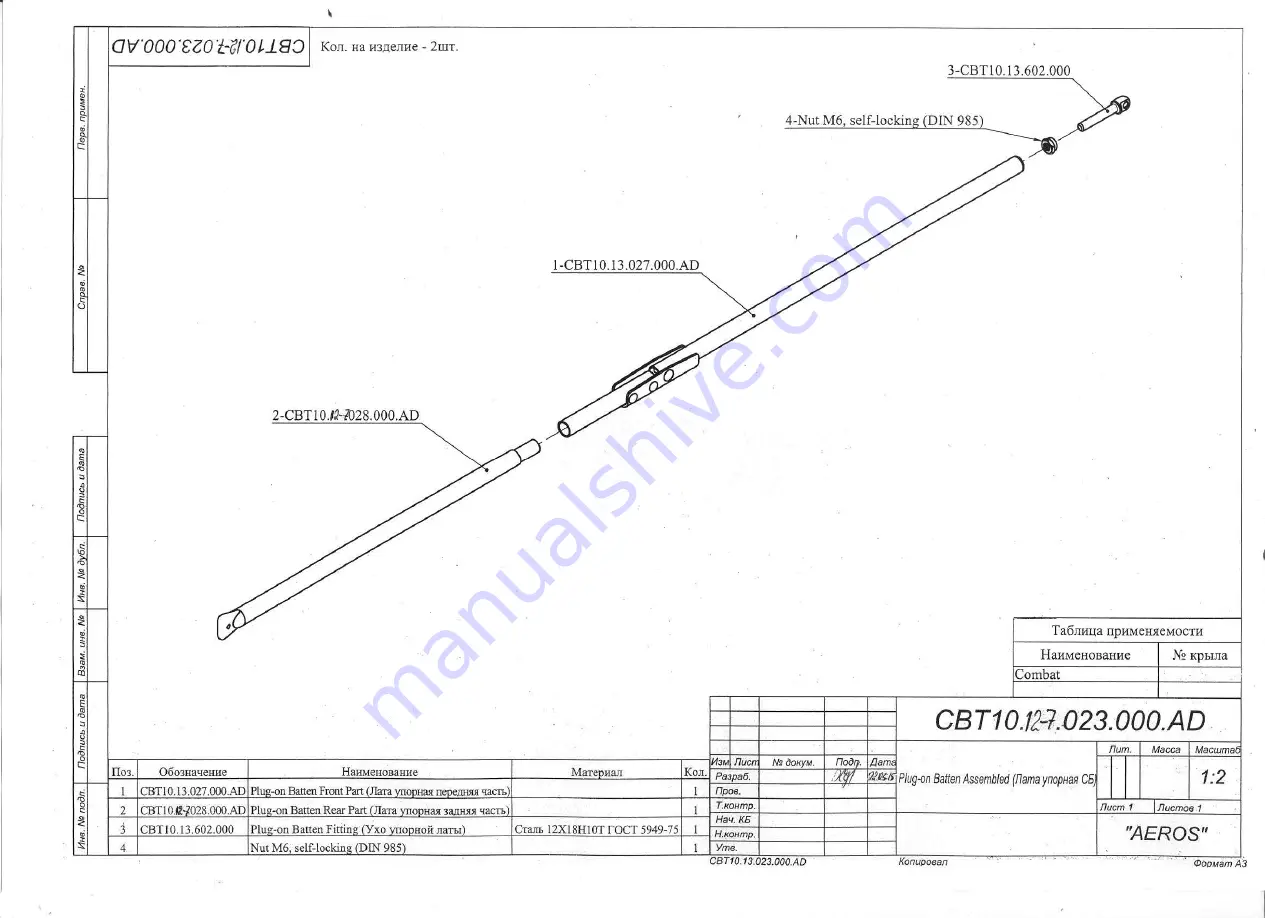
Page 36: ...on Batten Rear Part Лата упорная задняя часть 1 3 CBT10 13 602 000 Plug on Batten Fitting Ухо упорной латы Сталь 12Х18Н10Т ГОСТ 5949 75 1 4 Nut M6 self locking DIN 985 1 Кол на изделие 2шт Перв примен Н контр AEROS CBT10 13 023 000 AD 14 06 11 Нач КБ 1 2 CBT10 13 023 000 AD Разраб Копировал Формат А3 Утв Листов 1 Plug on Batten Assembled Лата упорная СБ Лист 1 Т контр Пров Дата Подп докум Лист Изм...

Page 37: ......

Page 38: ......

Page 39: ......

Page 40: ......

Page 41: ......

Page 42: ......

Page 43: ...Масштаб Масса Лит Перв примен 54 Washer M6 DIN 125 E 1 2 14 CBT07 119 000 48 Blind Rivet d4 8x14 A2 20 STL 122 013 23 STL 154 000 15 CBT07 13 637 000 42 STD 0033 C 15 0020 414 003 54 Washer M6 DIN 125 49 Nut M6 self locking DIN 985 55 Washer M8 DIN 125 19 DSC14A 114 000 25 STL 181 000 50 Nut M8 self locking DIN 985 25 STL 181 000 43 Болт 8 66 SPH 54 Washer M6 DIN 125 51 Safety Ring SBR1011 22 STL ...

Page 44: ......

Page 45: ...BT09 110 001 AD Разраб Копировал Формат А3 Утв Листов 1 1 4 Лист 1 Т контр Пров Дата Подп докум Лист Изм Масштаб Масса Лит Подпись и дата Инв дубл Взам инв Подпись и дата Инв подл Справ Н контр Кол на изделие 1шт Tapping Screw 2 2x6 5 Washer M3 DIN 125 A2 Left CBT09 111 002 AD CBTL 13 114 000 CBTL 13 114 000 Safety Ring SBR1011 STL 133 000 Safety Ring SBR1011 Blind Rivet d4 8x8 A2 Right CBT09 111 ...

Page 46: ... Screw 4 2x13 4 STL 132 000 2 CBTL 13 132 000 A 1 2 1 STL 116 000 AD 9 CBT10 13 131 001 AD A B Подпись и дата Подпись и дата CBT10 13 130 001 AD Разраб Инв подл Взам инв Лит Инв дубл Справ 20 01 11 CBT10 13 130 001 AD Нач КБ 1 5 Труба 3 правая СБ AEROS Перв примен Копировал Формат А3 Утв Н контр Листов 1 Лист 1 Т контр Пров Дата Подп докум Лист Изм Масштаб Масса Tube 3 Right Assembled CBT10 13 130...

Page 47: ...1011 5 Pin 4х28 26 9 PBF D 25 4 100 7 Safety Ring SBR1011 3 CBT09 12 161 000 Поз Обозначение Наименование Материал Кол 1 CBT07 13 163 000 AD Wire Internal Sprog Трос корневого АПУ 1 2 STL 169 000 AD Washout Eye Bolt Болт ушковый с ШС 1 3 CBT09 12 161 000 Tube Труба Труба Д16Т d25х1 ОСТ192096 83 1 4 CBTL 13 164 000 Sprog Threaded Adjuster Втулка АПУ Пруток Д16Т кр 25 ОСТ 190395 91 1 5 Pin 4х28 26 P...

Page 48: ...1011 2 STL 169 000 AD 6 STL 244 003 1 CBT07 13 163 000 AD 3 CBT07 13 161 000 Поз Обозначение Наименование Материал Кол 1 CBT07 13 163 000 AD Wire Internal Sprog Трос корневого АПУ 1 2 STL 169 000 AD Washout Eye Bolt Болт ушковый с ШС 1 3 CBT07 13 161 000 Tube Труба Труба Д16Т d25х1 ОСТ192096 83 1 4 Pin 4х28 26 Pin Валик Круг В8 30ХГСА ГОСТ 2590 88 1 5 CBTL 13 164 000 Sprog Threaded Adjuster Втулка...

Page 49: ...2 13 204 000 7 Safety Ring SBR1011 2 STL 169 000 AD 3 CBT07 13 141 000 Поз Обозначение Наименование Материал Кол 1 CBT07 13 142 000 AD Wire Outboard Sprog Трос концевого АПУ 1 2 STL 169 000 AD Washout Eye Bolt Болт ушковый с ШС 1 3 CBT07 13 141 000 Tube Труба Труба Д16Т d18х1 ОСТ192096 83 1 4 CBT2 13 204 000 Clevis Pin Валик 4х23 5 Круг В8 30ХГСА ГОСТ 2590 88 1 5 CBTL 13 143 000 Washout Threaded A...

Page 50: ...Сap Заглушка Полиамид ПА 12 10 6 ОСТ 05 425 76 1 3 CBT09 12 189 003 WD 4 STL 101 005 Справ Н контр CBT09 12 189 000 AD CBT09 12 189 000 AD Листов 1 Перв примен AEROS 17 06 10 Нач КБ 2 35 CBT09 12 189 000 AD Разраб Копировал Формат А3 Утв Keel Tube Assembled Килевая труба СБ 1 5 Лист 1 Т контр Пров Дата Подп докум Лист Изм Масштаб Масса Лит Подпись и дата Инв дубл Взам инв Подпись и дата Инв подл К...

Page 51: ......

Page 52: ......

Page 53: ......

Page 54: ...CBT 200 000 AD ...

Page 55: ...CBT 200 000 AD ...

Page 56: ...CBT 200 000 AD ...

Page 57: ...CBT2 220 000 AD ...

Page 58: ...CBT07 13 280 000 AD Combat 12 7 CBT07 14 280 000 AD Combat 13 5 CBT09 13 271 000 AD Combat 12 7 CBT09 14 271 000 AD Combat 13 5 CBT09 270 000 AD ...

Page 59: ...Combat GT 13 5 STL 263 000 ...

Reviews: