Neither the software nor the documentation may
be used for real aviation and training purposes.
07<15
page
DA20-100 ‘Katana’ 4X Manual
DESCRIPTION
7.10. FUEL SYSTEM
ENGINE COMPARTMENT
CABIN
FUEL COMPARTMENT
Fuel Quanity
Indicator
Return Line
Fuel Pressure
Warning Light
Pressure
Sensor
Oriface
Carburetor
Fuel Distribution
Manifold
Mechanical Fuel Pump
Carburetor
Supply Line
Fuel Shut-Off
Valve
Vent Line
Ball Valve
Electric Fuel Pump
Filler
Signal Line
Fuel Drain Valve
Fuel Drain Tube
Fuel Sender
Finger Filter
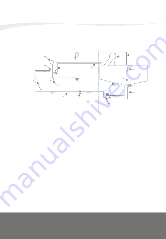
The tank, made from aluminum, is located behind the seats, below the
baggage compartment. It holds 76 liters (20.1 US gal.), of which 74 liters
(19.5 US gal.) are usable. The tank filler on the left side of the fuselage
behind the canopy is connected to the tank with a rubber hose. The tank
vent line runs from the filler connection piece through the fuselage bottom
skin to the exterior of the airplane .
A finger filter is installed at the bottom of the tank. From there, the fuel is fed
to the electric fuel pump, and from there, through the middle tunnel to the
fuel shut-off valve. From the fuel shut-off valve it is fed to the firewall breach,
and further to the mechanical fuel pump. From there, the fuel reaches the
distribution manifold and finally the float chambers of both carburetors. A
return line runs from the distribution manifold to the tank. Incorporated in
the return line is an orifice.
A fuel pressure sensor is installed at the distribution manifold. As soon as
the fuel pressure drops below 0.1 bar (1.5 psi), the fuel pressure warning
light will illuminate.
Summary of Contents for DA20-100
Page 1: ...MANUAL DA20 100 Katana ...
Page 2: ......


