background image

CHT-100 Cylinder Head Temperature Indicator 

Page 11 of 11


Aerospace Logic Inc. 

3150 Ridgeway Drive, Unit #43, Mississauga, Ontario, L5L 5R5, CANADA 

Tel. (905) 569-3887 | Fax. (416) 352-5854 | Email. sales@aerospacelogic.com 

www.aerospacelogic.com 

CHT-100 Operations & Installation Manual – Ver. 1.9 – June 5, 2003


7.   CHT-100 Specifications 


Dimensions


Fits standard 2.25” mounting hole 


2.45” X 2.45” X 1.60” 


2” viewing area 


Weight: 10oz (4 cyl.) / 13oz (6 cyl.) 


Display 


Custom design color bar display 


Multi-color sunlight visible 


InGaAIPGaN LED technology 


100,000 hours operating life 


Analog and digital readout of temperatures 


Maximum Ranges 


0ºF – 700ºF. Displays 100ºF – 700ºF as 
actual temperature and 0ºF – 99ºF as 
“COLD” 


Voltmeter: 6.0v to 32v (optional) 


Accuracy 


1% of range per TSO (SAE AS8005 Class 
IIa instrument classification) 


Voltmeter: 1/10 Volt over full operating 
range 


Safety 


Color coded temperature values 


Visual high temperature alarms for each 
cylinder 


Dual processor monitoring with one second 
error shutoff 


Internal over temperature shutoff 


Floating point mathematical compensation 
for thermocouple sensor linearity 


Minimum 256 times measurement 
validation before display 


Operating Temperature 


-15C to +55C 


5F to 131F 


Power Consumption 


370mA Max (daytime operation)  


50mA Min (nighttime operation)


Display Units 


ºF – temperature 


Volts – voltmeter (optional) 


Display Pages/Functions 


AUTO – automatically select and display 
hottest cylinder. One second scan rate for 
4/6 cylinders 


STEP – sequentially step through each 
cylinder with five second intervals 


1 – 4/6 – manually select and display any 
cylinder information 


High limit alarms (visual) 


Integrated voltmeter (optional) 


Two brightness selection pages (internal 
intensity selection) 


Intensity Control 


Programmable user option 


External using rheostat type dimmer 


Internal selection programmable from the 
front panel 


256 level of brightness 


Linearity 


Mathematical compensation over the full 
operating range 


Operating Voltage 

 6V-32V 

DC 


Thermocouples Supported 


ONLY TSO’d thermocouples that possess the 

following characteristics: 


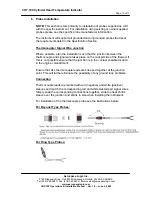
Recommended type Westach series 713 CHT 
probes (either bayonet or ring type): 


Type J with outputs as listed: 


100ºF – 0.72mV 


200ºF – 3.69mV 


300ºF – 6.72mV 


400ºF – 9.81mV 


500ºF – 12.90mV 


600ºF – 15.96mV 


700ºF – 19.04mV


All specification subject to change 

© 2002-2003 Aerospace Logic Inc.


Summary of Contents for CHT-100

Page 1: ...0 Cylinder Head Temperature Indicator This instrument is a complex precision instrument manufactured to exceed Airborne Equipment Standards DO 160D DO 178B and TSO C43c standards In order for your ins...

Page 2: ...o ensure that it is functioning correctly In turn the main processor validates the independent monitoring processor Any failure detected in either processor and your instrument display will be shut do...

Page 3: ...sure proper operation The instrument has been software calibrated and never needs recalibration provided no wiring modifications are made at installation time Now connect the supply and dimmer wiring...

Page 4: ...r 4 RED Cylinder 2 GREEN Cylinder 5 WHITE Cylinder 3 YELLOW Cylinder 6 If you have purchased a complete instrument and probe kit appropriate connectors for interconnection of the signal wires and prob...

Page 5: ...Page 5 of 11 Aerospace Logic Inc 3150 Ridgeway Drive Unit 43 Mississauga Ontario L5L 5R5 CANADA Tel 905 569 3887 Fax 416 352 5854 Email sales aerospacelogic com www aerospacelogic com CHT 100 Operati...

Page 6: ...n the setup mode the display bar will remain blank The CYL digit and the four digit display shows the parameter value and type as per the enclosed instructions In order to set the manufacturer specifi...

Page 7: ...tch once to the S position and release The low limit will now be saved and applied to all cylinders The display will move to the next parameter H High Temperature Limit Set The high temperature limit...

Page 8: ...isplay the STEP message for approximately five seconds before starting the step process Once started it will step through all cylinders When the last is reached it will revert back to the first 1 Disp...

Page 9: ...his mode of operation is the single most important feature of this instrument and should be used for all leaning and cooling function If the instrument is switched from the automatic mode back to the...

Page 10: ...mocouple Signal Wire Junction Where possible plan the installation such that the junction between the thermocouple and signal wire takes place on the cockpit side of the firewall If this is not possib...

Page 11: ...sation for thermocouple sensor linearity Minimum 256 times measurement validation before display Operating Temperature 15C to 55C 5F to 131F Power Consumption 370mA Max daytime operation 50mA Min nigh...

Reviews: