CHT-100 Cylinder Head Temperature Indicator
Page 3 of 11
Aerospace Logic Inc.
3150 Ridgeway Drive, Unit #43, Mississauga, Ontario, L5L 5R5, CANADA
Tel. (905) 569-3887 | Fax. (416) 352-5854 | Email. sales@aerospacelogic.com
www.aerospacelogic.com
CHT-100 Operations & Installation Manual – Ver. 1.9 – June 5, 2003
3. Installation
Ensure that the thermocouple probes have been installed PRIOR to installing the
instrument.
See Probe Installation for full details (Section 6).
The CHT-100 will fit any standard 2 ¼” aircraft mounting hole. Place the
instrument in the hole from the rear of the panel and then attach it with the four
screws provided. If you need to replace the screws, ensure that the threads do
not penetrate the instrument more than ½”. Screws that penetrate the instrument
further will cause severe damage to the instrument.
WARNING
This instrument is a highly sensitive and accurate instrument, however without
proper wiring and connections it is possible to induce temperature reading errors.
Please read and follow all instructions carefully to ensure proper operation.
The instrument has been software calibrated and never needs recalibration
provided no wiring modifications are made at installation time.
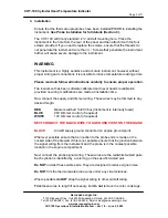
Now connect the supply and dimmer wiring. These wires may be trimmed to any
desired length.
RED
Master switched 14/28V bus (Instrument is internally fused)
BLUE
28V Dimmer control (if required)
WHITE
14V Dimmer control (if required)
NEXT CONNECT THE BLACK WIRE TO A GROUND POINT ON THE ENGINE
BLACK
Aircraft supply ground connected on engine ground point.
Wherever possible ensure that connection to the probe ends is made on the
cockpit side of the firewall. If this is not possible ensure that the junction between
the signal wiring from the instrument and the probe is in the coolest possible
location in the engine compartment.
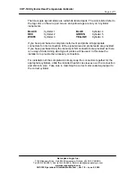
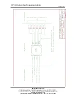
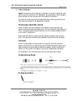
Next connect the probe signal wiring. These wires are the red/white twisted pairs.
Each cylinder is identified by a color tag on the specific twisted pair.
Do NOT
un-twist these cable pairs. They are designed to reduce signal noise.
Do NOT
trim the thermocouple probe wires under any circumstances.
Where possible
do NOT
strap the signal wiring to other aircraft wiring.
Trim
these wires to length if necessary, but
do not
remove the color code tags.

