background image

EGT-100 Exhaust Gas Temperature Indicator 

Page 4 of 11


Aerospace Logic Inc. 

3150 Ridgeway Drive, Unit #43, Mississauga, Ontario, L5L 5R5, CANADA 

Tel. (905) 569-3887 | Fax. (416) 352-5854 | Email. sales@aerospacelogic.com 

www.aerospacelogic.com 

EGT-100 Operations & Installation Manual – Ver. 1.9 – June 5, 2003 


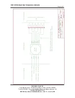
Thermocouple signal cables are red/yellow twisted pairs. The colors listed refer 
to the tag color on the wire pair. Green and yellow tags are only on 6 cylinder 
instruments. 
 

BLACK


Cylinder 1 


BLUE


Cylinder 4 

RED


 Cylinder 


GREEN

 Cylinder 

WHITE


 Cylinder 


YELLOW

 Cylinder 

 
If you have purchased a complete instrument and probe kit appropriate 
connectors for interconnection of the signal wires and probe leads are provided. 
If you have purchased only the instrument NO connectors are provided as there 
is no way of determining what type of probes will be used. In this case the 
installer is to provide the necessary connectors. 

WARNING! TSO and STC 

certifications for this instrument will be void if it is used in conjunction with 
NON-TSO’d thermocouples! See Specifications for requirements.


For installation of the complete kit, simply snap the connectors together for the 
appropriate cylinders, slide the included heat shrink sleeves over the connection 
and shrink to size.  Take care in matching the correct color coded signal pair to 
the correct cylinder. 


Summary of Contents for EGT-100 Series

Page 1: ...0 Exhaust Gas Temperature Indicator This instrument is a complex precision instrument manufactured to exceed Airborne Equipment Standards DO 160D DO 178B and TSO C43c standards In order for your instr...

Page 2: ...ensure that it is functioning correctly In turn the main processor validates the independent monitoring processor Any failure detected in either processor and your instrument display will be shut down...

Page 3: ...ure proper operation The instrument has been software calibrated and never needs recalibration provided no wiring modifications are made at installation time Now connect the supply and dimmer wiring T...

Page 4: ...e purchased a complete instrument and probe kit appropriate connectors for interconnection of the signal wires and probe leads are provided If you have purchased only the instrument NO connectors are...

Page 5: ...Page 5 of 11 Aerospace Logic Inc 3150 Ridgeway Drive Unit 43 Mississauga Ontario L5L 5R5 CANADA Tel 905 569 3887 Fax 416 352 5854 Email sales aerospacelogic com www aerospacelogic com EGT 100 Operatio...

Page 6: ...the setup mode the display bar will remain blank The CYL digit and the four digit display shows the parameter value and type as per the enclosed instructions In order to set the manufacturer specified...

Page 7: ...ch once to the S position and release The low limit will now be saved and applied to all cylinders The display will move to the next parameter H High Temperature Limit Set The high temperature limit s...

Page 8: ...splay the STEP message for approximately five seconds before starting the step process Once started it will step through all cylinders When the last is reached it will revert back to the first 1 Displ...

Page 9: ...nt and should be used during leaning and normal operations Leaning in the automatic mode ensures that no cylinder is overheated during the process If the instrument is switched from the automatic mode...

Page 10: ...Section Thermocouple Signal Wire Junction Where possible plan the installation such that the junction between the thermocouple and signal wire takes place on the cockpit side of the firewall If this i...

Page 11: ...for thermocouple sensor linearity Minimum 256 times measurement validation before display Operating Temperature 15 C to 55 C 5 F to 131 F Power Consumption 370mA Max daytime operation 50mA Min nightt...

Reviews: