16
G
B
and to the electrovalve if any) carried out by qualified personnel.
•
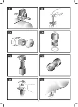
Check the oil level using the sight glass and if necessary unscrew the vent
plug and top up. (
figures 7a-7b
).
• At this point, the compressor is ready for use.
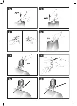
• Operating on the switch of the pressure switch (or the selector for versions with
electric panel), (
figures 6a-6b-6c-6d
), the compressor starts, pumping air in
the reservoir through the delivery hose. On 2-stage versions, air is sucked into
the so-called low pressure cylinder liner and precompressed. It is then routed,
through the recirculation hose, into the so-called high pressure liner and then
into the reservoir. With this work cycle, it is possible to reach higher pressure,
with availability of air at 11 bar (15 bar for special machines).
• On reaching maximum operating pressure (factory-set during testing), the
compressor stops, venting the excess air present in the head and in the delivery
hose through a valve located under the pressure switch (in delta/star versions,
through an electrovalve that is activated when the motor stops).
• The absence of pressure in the head facilitates subsequent restart.
When air is used, the compressor restarts automatically when the lower
calibration value is reached (approx. 2 bar between upper and lower).
The pressure inside the reservoir can be checked on the gauge provided
(
fig. 4a-4b
).
•
The compressor continues to operate automatically with this work cycle until
the position of the switch of the pressure switch (or of the selector of the electric
panel) (
figures 6a-6b-6c-6d
) is modified. To use the compressor again, wait at
least 10 seconds after this has been switched off before restarting.
• In the versions with electric panel, the pressure switch must always be aligned
with the
I
(
ON
) position.
• In tandem versions, the control unit provided permits use of only one of the
two compressor groups (if necessary alternatively) or of both at the same time
according to requirements. In this second case, start-up will be differentiated
slightly to avoid excessively high current take-off at start-up (timed starting).
• Only the wheel-mounted compressors are fitted with a pressure reducer (in
the versions with fixed feet, it is usually installed on the use line). Air pressure
can be regulated in order to optimize use of air-powered tools operating on the
knob with the valve open (pulling it up and turning it in a clockwise direction
to increase pressure and counterclockwise to reduce this) (
fig. 8
). Once you
have set the value required, push the knob down to lock it.
• The value set can be checked on the gauge (for versions equipped with this,
fig. 9
).
•
Please check that the air consumption and the maximum working pressure
of the pneumatic tool to be used are compatible with the pressure set on the
pressure regulator and with the amount of air supplied by the compressor.
• When you have finished working, stop the machine, pull out the plug and
empty the reservoir.
3. MAINTENANCE
• The service life of the machine depends on maintenance quality.
•
PRIOR TO ANY OPERATION SET THE PRESSURE SWITCH TO THE
OFF POSITION, PULL OUT THE PLUG AND COMPLETELY DRAIN THE
RESERVOIR.
• Check that all screws (in particular those of the head of the unit) are tightly
drawn up (
fig. 10
).
The control must be performed before the first start-up of the compressor and
subsequently before the first intensive use in order to restore the correct closing
torque value modified as a result of heat expansion.
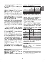
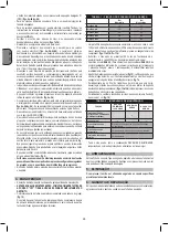
TABLE 1 – TIGHTENING OF HEAD TENSION RODS
Nm
Min. torque
Nm
Max. torque
Screw M6
9
11
Screw M8
22
27
Screw M10
45
55
Screw M12
76
93
Screw M14
121
148
• Clean the suction filter according to the type of environment and in any case at
least every 100 hours. If necessary, replace the filter (a clogged filter impairs
efficiency while an inefficient filter causes harsher wear on the compressor
(
figures 11a - 11b-11c-11d
).
• Change the oil after the first 100 hours of operation and subsequently every
300 hours. Check the oil level periodically.
•
Use
SAE 40
. (For cold climates,
SAE 20
is recommended). Never mix different
grade oils. If the oil changes color (whitish = presence of water; dark = overheated),
it is good practice to replace the oil immediately.
• After topping up, tighten the plug (
fig. 12
) making sure that there are no leaks
during use. Once a week, check the oil level to assure lubrication in time (
fig. 7a
).
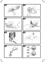
• Periodically (or after completing work if for more than an hour), drain the
condensate that forms inside the reservoir due to the humidity in the air (
fig.
13a-13b
) in order to protect the reservoir from rust and so as not to restrict
its capacity.
• Periodically, check the tension of the belts which must have a flexion (f) of
around 1 cm (
fig. 14
).
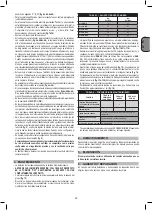
TABLE 2 – MAINTENANCE
FUNCTION
AFTER THE
FIRST 100
HOURS
EVERY 100
HOURS
EVERY 300
HOURS
Cleaning of intake filter and/
or substitution of filtering
element
•
Change of oil*
•
•
Tightening of head tension
rods
The check must be carried out prior to the first
compressor starting.
Draining tank condensate
Periodically and at the end of work
Checking the tension of
the belts
Periodically
* Spent oil and condensate MUST BE DISPOSED OF in compliance with protection
of the environment and current legislation.
4. STORAGE
Pull the mains plug out of the socket and ventilate the appliance and all
connected pneumatic tools. Switch off the compressor and make sure that it is
secured in such a way that it cannot be started up again by any unauthorized
person.
5. DISPOSAL
The compressor must be disposed in conformity with the methods
provided for by local regulations.
6.
WARRANTY AND REPAIR
In the event of defective goods or requirements for spare parts, kindly contact
the sales point where you made your purchase.
Summary of Contents for 290-20
Page 7: ...7 ON ON 2 3a 3c 1b 3b 4a 4b 1a...
Page 8: ...8 OFF ON 6a OFF ON 6c OFF ON 6b 5 6d OFF ON 8 7a 7b...
Page 9: ...9 11b 11a 10 9 11c 11d 12 13a...
Page 10: ...10 13b 14 15a 15b 16 17a 17b 17c...
Page 11: ...11 18 19 20 21a 21b...
Page 42: ...42 G R 1 5 C 40 C 4 5 50 cm S3 50 5 5 1a 1b 2 3a 3b 3c 4a 4b 5 7 bar...
Page 44: ...44 G R 7 15a 15b rilsan rilsan 16 11a 11b 11c 11d 14 17a 17b 17c 1a 2 1b 3c 6d 1a 1b 18...
Page 63: ...63 R U 1 5 C 40 C 4 5 50 S3 50 5 5 1a 1b 2 3a 3b 3c 4a 4b 5 7 2 19 20 21...
Page 65: ...65 R U 7 15a 15b 16 11a 11b 11c 11d 14 17a 17b 17c 1a 2 1b 3c 6b 1a 1b 18...
Page 75: ...75 B G 1 5 C 40 C 4 5 50 S3 50 5 5 1a 1b 2 3a 3b 3c 4a 4b 5 7bar...
Page 77: ...77 B G 7 15a 15b 16 C C 11a 11b 11c 11d 14 17a 17b 17c 1a 2 1b 3c 6d 1a 1b 18...
Page 90: ...90...
Page 91: ...91...
Page 92: ...9039203 A...

