INTRODUCTION
These introductions are provided to guide the operator in the safe and correct use of the product and
must be stored in a clearly indicated place nearby for easy and rapid consultion. Please read this
introduction before use.
INSTRUCTIONS FOR USE (FX Serie ¼’’ - 1’’)
GENERAL RULES FOR INSTALLATION, USE AND MAINTENANCE
The System should be installed as near as possible to the utilization point, and in the case of
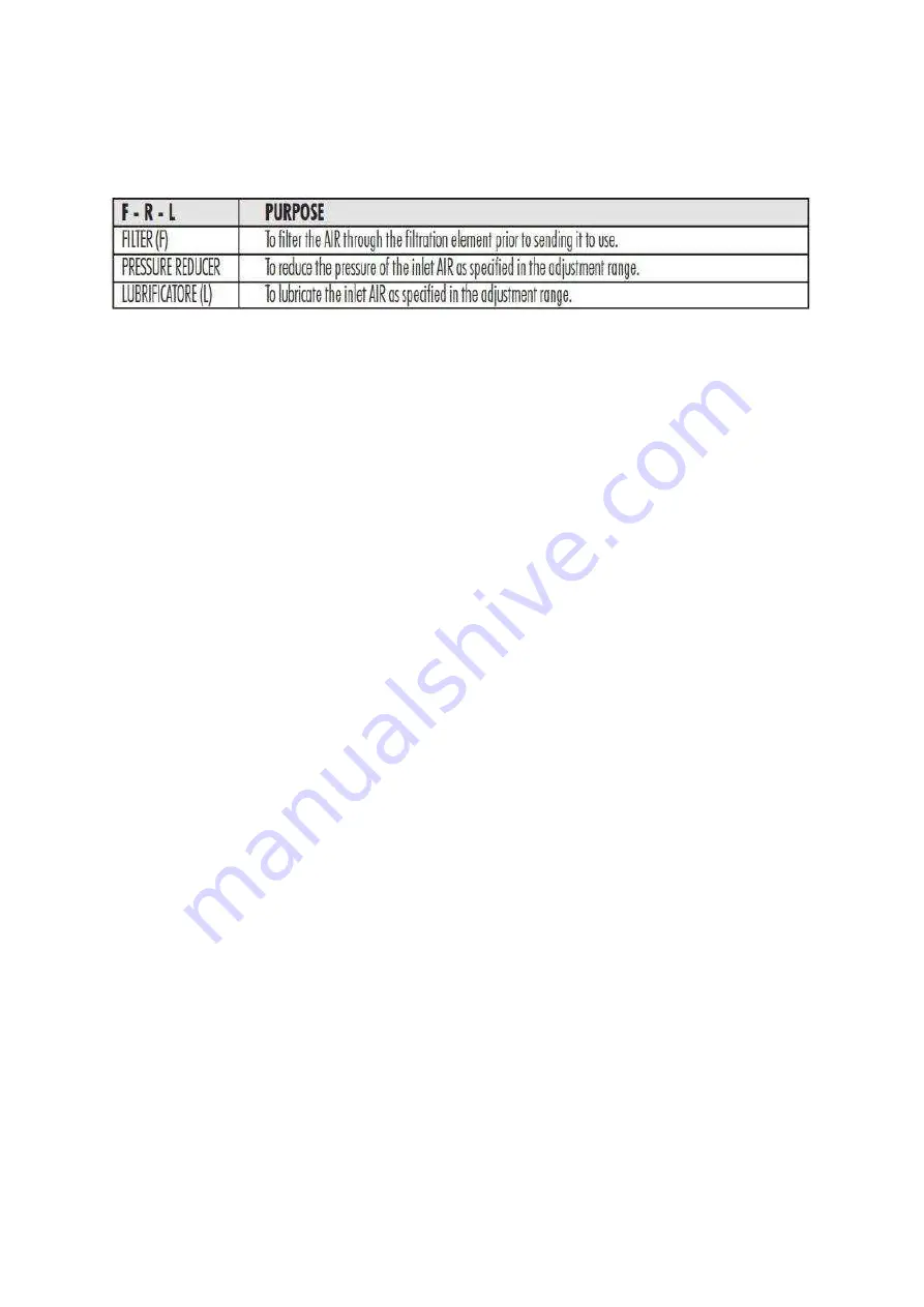
combining different units the sequence of 'Filter - Pressure Reducer - Lubricator' must respected.
NOTE: FOR BOTH SINGLE AND COMBINATION ELEMENTS, MAKE SURE THAT THE AIR
FLOWS IN THE DIRECTION SHOWN BY THE ARROWS.
Use only the appropriate unit connector plates, o-rings and connection screws to assemble the single
elements. Where installing on a wall, mount the supports at the end of the System units using the
screws provided.
TECHNICAL DATA: Maximum inlet air pressure: 12 bar (FX Series 1/4") - 14 bar (FX Series 1/2") -
16 bar (FX Serie).
Maximum temperature: 60°C (at maximum pressure). Filtration element: 10 µ
Pressure reducer adjustment range: 0 + 8 bar (FX Series 1/4") 0 + 10 bar (FX Series 1/2") 2 + 14 bar
(FX Series 1")
Lubricator adjustment range: 1 drop every 300 + 600 L/min.
USE: fill the lubricator directly by unscrewing the oil cup or through the opening in the plug before to
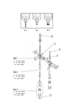
pressurizing the system. Only use ISO and UNI FD oils. Adjust pressure by turning the upper knob (B)
of the pressure reducer and proceeding as follows: pull the knob upwards in order to permit rotation.
Rotate the knob clockwise in order to increase the working pressure and counter clockwise in order to
decrease the working pressure. When the desired pressure has been reached, push the knob down to
lock the knob in place. The monomer for indicating the working pressure can be either front or rear
mounted.
NOTE: Close the outlet(s) that are not being used with the threaded plug (C).
NOTE: the desired pressure is reached by giving a final rotation in the clockwise direction.
There is a tap (D) under the filter cup to discharge accumulated condensates. When the tap has been
turned to the central 'free' position (Pos.1), the tap will work semi-automatically. i.e. the valve is closed
when the system is under pressure and the valve will discharge condensates automatically when the
system is not pressurized.
There is a tap (D) under the filter cup to discharge accumulated condensates.
When the tap has been turned to the central 'free' position (Pos. 1) , the tap will work semi-
automatically. i.e. the valve is closed when the system is under pressure and the valve will discharge
condensates automatically when the system is not pressurized.
Accumulated condensates can be manually discharged by pushing the tap when it has been rotated to
position 2. Condensates must be discharged regularly.
To change the dosage of oil in the working air, use the knob on top of the oiler unit (E). Adjust the
knob on the lubricator in a counter-clockwise direction to increase or clockwise to decrease the
quantity of oil.
WARNINGS: The maximum inlet pressure must not exceed the values listed in the technical data.
Never expose the FRL System to sources of heat higher than 60°C. Avoid installing the FRL System
in positions subject to shock, vibration, or other types of physical, chemical or mechanical stress.
Avoid installing the FRL system wherever there are strong concentrations of alcohol or solvents.
Use only soap and water to clean the cups. Do not use: detergents, oils, brake fluid oils, or solvents in
general. Regularly discharge the condensate that forms in the filter cup.
NOTE: never unscrew the cups or other parts without first depressurizing the system.
WARNING! KEEP OUT OF REACH OF CHILDREN.
IMPORTANT! Incorrect use can damage the product. The user must therefore scrupulously observe
the contents and instructions of this booklet. The Manufacturer declines all responsibility for the
incorrect use of the system.

