4/28/2021
Nano Shutter User Guide : Aeotec Help Desk
https://aeotec.freshdesk.com/support/solutions/articles/6000198854-nano-shutter-user-guide-
3/15
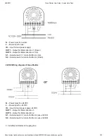
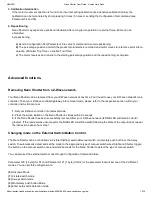
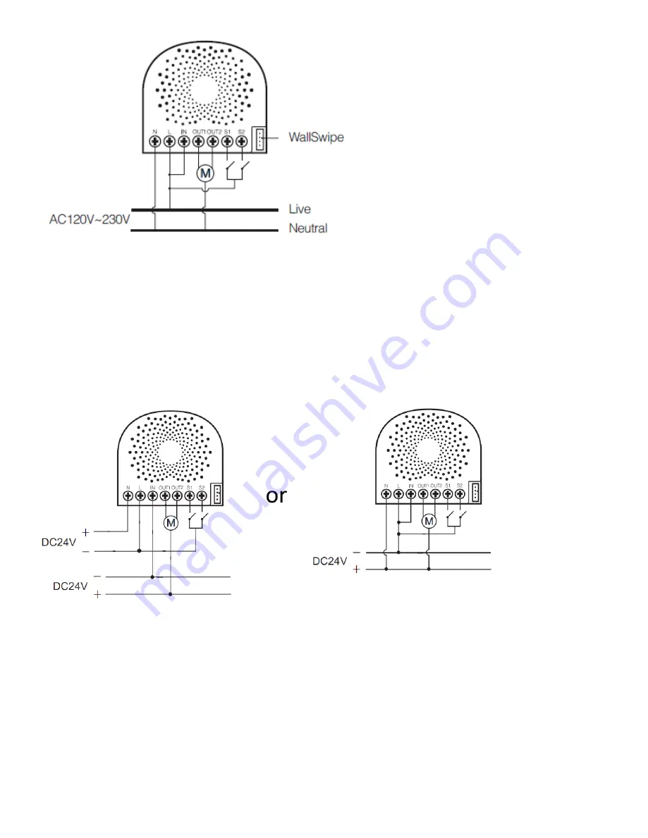
N
– Power input for neutral.
L
– Power input for live.
IN
– Input for load power supply.
OUT1
– Output for Motor direction 1. (Down)
OUT2
– Output for Motor direction 2. (Up)
S1
– External switch 1 control for Motor. (Up)
S2
– External switch 2 control for Motor. (Down)
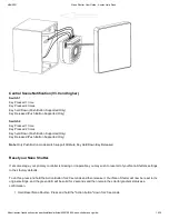
24VDC Wiring diagram of Nano Shutter.
N
– Power input for +24VDC
L
– Power input for -24VDC
IN
– Input for load power supply -24VDC.
OUT1
– Output for Motor direction 1.
OUT2
– Output for Motor direction 2.
S1
– External switch 1 control for Motor. (use -24VDC)
S2
– External switch 2 control for Motor. (use -24VDC)
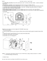
3. Install Nano Shutter to the gang box.

