4/28/2021
Nano Shutter User Guide : Aeotec Help Desk
https://aeotec.freshdesk.com/support/solutions/articles/6000198854-nano-shutter-user-guide-
4/15
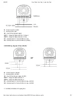
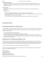
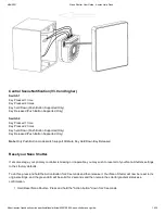
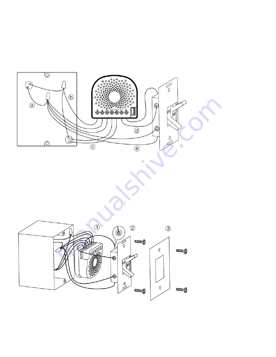
a. Live/Hot wire connection:
Connect the Live/Hot wire to the “L” terminal on the Nano Shutter. + Live/Hot on External
Switch input.
b. Neutral wire connection:
Connect the Neutral wire to the “N” terminal on the Nano Shutter.
b. Load wire neutral connection (To AC Neutral):
Connect the Load/Motor neutral wire to your AC Neutral connection.
c. Load wire motor connection (To Nano Shutter):
Connect the 2 Load/Motor wires (Motor direction 1 and Motor
direction 2) to "OUT1" and "OUT2" on Nano Shutter.
d. External/manual Switch connection:
Connect 2 18AWG wires to the “S1” and “S2” on the Nano Shutter.
d.
External/manual Switch connection:
Connect 2 18AWG wires form the 2 terminals on the External/manual Switch to
the Live wire.
Note:
This is the physical connection diagram for 120/230VAC power input.
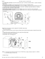
1. Mounting the gang box.
2. Position all wires to provide room for the device. Place the Nano Shutter inside the gang box towards the back of the
box.
3. Position the antenna towards the back of the box, away from all other wirings.
4. Reinstall the Nano Shutter to the gang box.
5. Reinstall the cover onto the gang box.
Note:
1. The gang box should be sized 3×2×2.75 inch / 75×50×70 mm or larger, minimum volume 14 in / 230mm.
2. Use flexible copper conductors only.
5. Restore Power.

