Electrical Specifications and Installation
ABL1500WB-B Hardware Manual
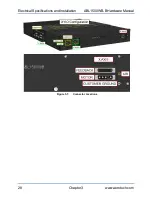
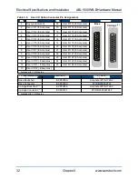
Table 3-3:
User I/O Option Connector Pin Assignments
Pin
Description
Pin
Description
Connector
1
Key (pin removed)
14
User I/O 13 (.8 Amp max)
Base
Carriage
(1)
2
User I/O 1 (.8 Amp max)
15
User I/O 14 (.8 Amp max)
3
User I/O 2 (.8 Amp max)
16
User I/O 15 (.8 Amp max)
4
User I/O 3 (.8 Amp max)
17
User I/O 16 (.8 Amp max)
5
User I/O 4 (.8 Amp max)
18
User I/O 17 (.8 Amp max)
6
User I/O 5 (.8 Amp max)
19
User I/O 18 (.8 Amp max)
7
User I/O 6 (.8 Amp max)
20
User I/O 19 (.8 Amp max)
8
User I/O 7 (.8 Amp max)
21
User I/O 20 (.8 Amp max)
9
User I/O 8 (.8 Amp max)
22
User I/O 21 (.8 Amp max)
10
User I/O 9 (.8 Amp max)
23
User I/O 22 (.8 Amp max)
11
User I/O 10 (.8 Amp max)
24
User I/O 23 (.8 Amp max)
12
User I/O 11 (.8 Amp max)
25
User I/O 24 (.8 Amp max)
13
User I/O 12 (.8 Amp max)
1. Available with -Y-CMS option
Mating Connector
Aerotech P/N
Third Party P/N
Base Backshell
ECK00656
Amphenol #17E-1726-2
Base Connector
ECK00300
FCI DB25S064TLF
Carriage Backshell
(1)
ECK00656
Amphenol #17E-1726-2
Carriage Connector
(1)
ECK00101
FCI DB25P064TXLF
1. Available with -Y-CMS option
32
Chapter 3
www.aerotech.com

