background image

Operating Specifications

ABL/ABLH9000 Series Stage User's Manual

3.3. Load Capability [TBD]

3.4. Limit Switch Wiring

ABL/ABLH9000 series stages are provided with a series of optical limit switch assemblies. The limit
switches signal when the stage has reached its maximum useable travel distance in all directions.

3.4.1. Limit Switch Operation

Each limit switch has a light source and detector mounted to a small printed circuit board. Each limit switch
board is mounted at the ends of an axis with their emitter–detector axes perpendicular to the direction of axis
motion. The limit switch itself can be configured as normally closed (NC) or normally open (NO).

If the stage is driven approximately 6 mm beyond the electrical limit, it will encounter a
mechanical stop. Although the operating speed of the stage may be relatively slow, damage
to the stage could result.

3.4.2. Limit Switch Wiring

Limit switches are open-collector, TTL–compatible, electro–optical devices powered by 5 Volts that change
output states when the stage approaches its maximum travel distance and breaks the light beam. Since they
are open-collector devices, they may be interfaced to 24Volt logic inputs. Each limit switch is mounted on a
small printed circuit board. Standard ABL/ABLH9000 Stages include limit switch wiring integrated into the
feedback connector.

Assuming a NC limit configuration, the input to the controller is seen as a logic 0 (typical 0.4V @ 12.8mA)
when no limit condition is present. When the limit switch is activated, a 5V source through a pull-up resistor
causes a logic 1 (typically 4.8-5V) to be seen by the controller input. The limit switch operation for a NO limit
configuration is the exact opposite as described above. See Figure 3-2 for a diagram of limit switch wiring.

Figure 3-2:

Normally Closed (NC) and Normally Open (NO) Limit Switch Wiring

16

Chapter 3

www.aerotech.com

Summary of Contents for ABL9000 Series

Page 1: ...L ABLH9000 Series Stage User s Manual P N EDS104 Revision 1 01 00 Dedicated to the Science of Motion Aerotech Inc 101 Zeta Drive Pittsburgh PA 15238 Phone 412 963 7470 Fax 412 963 7459 www aerotech co...

Page 2: ...Phone 49 911 967 9370 Fax 49 911 967 93720 Email service aerotechgmbh de Japan Phone 81 0 47 489 1741 Sales Phone 81 0 47 489 1742 Service Fax 81 0 47 489 1743 Email service aerotechkk com jp China P...

Page 3: ...hing the Payload to the Stage 9 2 5 Electrical Installation 9 2 6 Air Requirements 9 Chapter 3 Operating Specifications 11 3 1 Environmental Specifications 11 3 2 Basic Specifications 12 3 3 Load Capa...

Page 4: ...Table of Contents ABL ABLH9000 Series Stage User s Manual iv www aerotech com...

Page 5: ...ge 1 Figure 1 2 ABL ABLH9000 Series Stage 2 Figure 3 1 Velocity vs resolution as a function of system data rate ABL ABLH9000 with LTAS or LNAS encoder 14 Figure 3 2 Normally Closed NC and Normally Ope...

Page 6: ...List of Figures ABL ABLH9000 Series Stage User s Manual vi www aerotech com...

Page 7: ...le 3 1 Environmental Specifications 11 Table 3 2 ABL ABLH9000 Series Specifications 12 Table 3 3 ABL ABLH9000 Series Resolution Information 14 Table 3 4 ABL ABLH9000 Motor Specifications 15 Table 4 1...

Page 8: ...List of Tables ABL ABLH9000 Series Stage User s Manual viii www aerotech com...

Page 9: ...play and optical inspection and fabrication the ABL ABLH9000 sets new standards of performance This chapter introduces standard and optional features of the ABL ABLH9000 stages and gives general safet...

Page 10: ...both vertical and horizontal surfaces The opposing thin film pressure maintains the bearing nominal gap tolerance This design in addition to the large air bear ing surface that distributes the load ov...

Page 11: ...dual applications Common exam ples include cable management for stage mounted payloads custom tabletops and granite bases Contact the Aerotech factory for more details Table 1 1 Model Numbers and Orde...

Page 12: ...ly injury or death when any electrical circuit is in use ensure that no person comes in contact with the circuitry when the stage is connected to a power source To minimize the possibility of bodily i...

Page 13: ...lt in injury and damage to the equipment Use care when moving the stage Manually lifting or transporting stages can result in injury Only trained personnel should operate inspect and maintain the stag...

Page 14: ...1 2005 Safety of machinery Electrical equipment of machines Part 1 General requirements and further more declares that it is not allowed to put the equipment into service until the machinery into whi...

Page 15: ...ranite cleaner available from most granite suppliers Before the stage can be operated the shipping clamps must be removed These are the only red anodized parts on the stage and must all be removed To...

Page 16: ...assistance 2 3 Securing the Stage to the Mounting Surface All ABL ABLH9000 stages come mounted to a granite slab from the factory This granite is not only a part of the air bearing system but also el...

Page 17: ...cumentation regarding the stage wiring controller interface connectors and specs for each particular stage Never connect or disconnect any electrical component or connecting cable while power is appli...

Page 18: ...Installation ABL ABLH9000 Series Stage User s Manual 10 Chapter 2 www aerotech com...

Page 19: ...C 32 to 104 F in original shipping packaging Humidity Operating 40 percent to 60 percent RH The optimal operating humidity is 50 percent RH Storage 30 percent to 60 percent RH non condensing in origin...

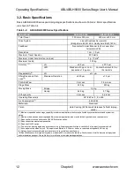
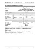
Page 20: ...0 kg 57 0 kg Orthogonality 2 arc sec 3 arc sec Operating Pressure 6 551 6 kPa 0 34 kPa Air Consumption 7 45 SLPM Material 8 Aluminum Finish Hard Coating 62 Rockwell Hardness Teflon Impreg nated 1 Max...

Page 21: ...onsumption 7 85 SLPM Material 8 Aluminum Finish Hard Coating 62 Rockwell Hardness Teflon Impregnated 1 Maximum speed based on stage capability maximum application velocity may be limited by system dat...

Page 22: ...rnal System Data Rate LZR 316 5 m 79nm Integral 8 500 mm s 1 LZR 316 5 m 3nm 15 8nm Requires External System Data Rate Code Maximum Speed Signal Type Encoder Connector LN System Data Rate LZR 500 mm s...

Page 23: ...4 12 60 N A rms 39 06 50 57 79 26 lb A rms 8 78 11 37 17 82 Motor Constant 2 4 N W 8 16 13 69 20 24 lb W 1 84 3 08 4 55 Resistance 25 C line to line Ohms 10 9 6 5 7 3 Inductance line to line mH 8 70 5...

Page 24: ...ge to the stage could result 3 4 2 Limit Switch Wiring Limit switches are open collector TTL compatible electro optical devices powered by 5 Volts that change output states when the stage approaches i...

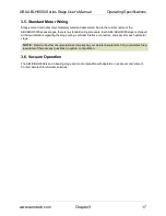
Page 25: ...hipped with documentation regarding the stage wiring controller interface connectors and specs for each particular stage N OTE Refer to the other documentation accompanying your Aerotech equipment Cal...

Page 26: ...Operating Specifications ABL ABLH9000 Series Stage User s Manual 18 Chapter 3 www aerotech com...

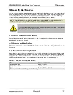
Page 27: ...vice and Inspection Schedule Aerotech recommends that the ABL ABLH9000 be inspected once per month until a trend develops for the specific application and environment 4 2 Cleaning and Lubrication Ther...

Page 28: ...entire encoder strip to be accessed for cleaning The cleaning process for the granite faces will differ depending on the type of cleaner purchased Follow instructions on the container for specific de...

Page 29: ...may be returned whether in warranty or out of warranty with out first obtaining approval from Aerotech No credit will be given nor repairs made for products returned without such approval Any returne...

Page 30: ...imes other than normal work periods then special service rates apply If during the on site repair it is determined the problem is not warranty related then the terms and conditions stated in the follo...

Page 31: ...hanges 1 01 00 Section s Affected General Information Section 1 3 Added section Section 3 1 Added section Chapter 2 Installation Section 2 1 and Sec tion 1 2 Added safety information and warnings Sect...

Page 32: ...Technical Changes ABL ABLH9000 Series Stage User s Manual Table B 2 Archived Changes Revision Section s Affected General Information 1 00 00 New manual 24 Appendix B www aerotech com...

Page 33: ...ications 11 I Inspection Schedule 19 L Limit Switch Wiring 16 Lubrication 19 M model numbers 7 O Optional Features 3 P Preparing the Mounting Surface 8 S safety procedures 4 Securing the Stage to the...

Page 34: ...ABL ABLH9000 Series Stage User s Manual Index 26 Index www aerotech com...

Page 35: ...ized Clearly presented Well illustrated How do you use this document in your job Does it meet your needs What improvements if any would you like to see Please be specific or cite examples Stage Produc...

Page 36: ......
Reviews: