Chapter 1: Overview
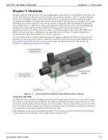
Aerotech’s AGV3D three-axis laser scan head manipulates a laser beam in three degrees of freedom: X, Y,
and Z. The AGV3D uses two mirrors, each of which is actuated by a galvano motor, to deflect the beam
in the X and Y directions. Before the X and Y deflections, the laser beam travels through the Dynamic
Focusing Module (DFM). The DFM uses an expander lens that is mounted on a high-dynamic linear stage
and stationary optics to adjust the focus the laser beam. Change the distance between the expander
lens and the optics to adjust the focal height (Z-height of the focused spot). Use this in field-flattening
applications to eliminate the need for expensive focusing optics such as an F-theta lens, or in
applications that require different working heights in different stages of the process. The DFM in the
AGV3D can also be used to collimate the incoming laser beam to function as a beam expander to
increase the incoming beam diameter to 2.5X the original size.
The scan head enclosure is fully sealed, featuring cover glass and gaskets over both the input and exit
apertures, to make sure that no dust or particles can infiltrate the enclosure and cause damage to the
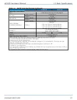
internal optical components. Only use a laser that meets the laser specifications that are listed in
Section 1.3. Basic Specifications
for details.
Figure 1-1:
Functional Principle of a 3-Axis Galvanometer Scanner
Integration Flexibility
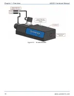
The AGV3D offers mounting flexibility, with mounting hole patterns on the side, rear, and bottom faces.
The control connections consist of two 300 mm cables terminated in 25-pin D-style connectors for the X
and Y axes, and an additional 25-pin D-style connector located on the top face of the enclosure for the Z
axis. The cables can be oriented in any direction and terminated on the machine to make sure that there
is no interference with beam delivery from the control cables.
A beam alignment fixture is included with the AGV3D. Bolt the fixture to the front face of the enclosure
to help align the input laser beam to the system (refer to
).
AGV3D Hardware Manual
Chapter 1: Overview
www.aerotech.com
15
Summary of Contents for AGV3D Series
Page 1: ...Revision 2 00 AGV3D Three Axis Laser Scan Head HARDWARE MANUAL...
Page 6: ...This page intentionally left blank List of Tables AGV3D Hardware Manual 6 www aerotech com...
Page 12: ...This page intentionally left blank Laser Shutter AGV3D Hardware Manual 12 www aerotech com...
Page 16: ...Figure 1 2 Standard AGV3D Chapter 1 Overview AGV3D Hardware Manual 16 www aerotech com...


