2.4. Securing the Scan Head to the Mounting Surface
WARNING
: It is the responsibility of the customer to safely and carefully move and mount
the scan head. If you are not careful, you could adversely affect the performance of the
AGV3D.
l
Make sure that all moving parts are secure before you move the AGV3D. Unsecured
moving parts could shift and cause injury or damage to the equipment.
l
To prevent contamination, make sure that the beam exit and the beam input aper-
ture are covered before you move the AGV3D.
l
Put the scan head on a soft surface when it is not attached to its mounting surface
to protect the optics.
The mounting surface should be flat and have adequate stiffness in order to achieve the maximum
performance from the AGV3D scan head (
). When an AGV3D is mounted to a non-flat surface,
the scan head can be distorted as the mounting screws are tightened. This distortion will affect the
alignment between the galvano motors and decrease the overall accuracy of the scan head. Adjustments
to the mounting surface must be made before the scan head is secured.
Inspect the mounting surface for dirt or unwanted residue and clean if necessary. Use precision
flatstones on the mounting surface to remove any burrs or high spots. Clean the mounting surface with
a lint-free cloth and acetone or isopropyl alcohol and allow the cleaning solvent to completely dry.
Gently place the stage on the mounting surface.
WARNING
: The AGV3D is precision machined and verified for flatness at the factory.
l
Do not machine the AGV3D housing. If you must machine a surface to achieve a
required flatness, machine the mounting surface.
l
Keep the use of shims to a minimum when you mount the AGV3D to the mounting
surface. The use of shims could reduce the rigidity of the system.
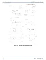
The AGV3D has three mounting options (
). The system should be mounted so that it is parallel
to the workpiece (refer to
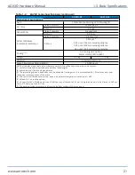
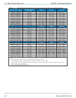
for the parallel mounting specification). Use the bottom of the exit
cover glass bracket as a reference, if possible. If this surface is inaccessible, use the unused mounting
points for reference. For example, if the rear mounting points are used to mount the AGV3D to the
mounting surface, use the bottom mounting points as a reference. Either the exit cover glass bracket or
the bottom mounting surface must be accessible to verify mounting parallelism.
AGV3D Hardware Manual
2.4. Securing the Scan Head to the Mounting Surface
www.aerotech.com
35
Summary of Contents for AGV3D Series
Page 1: ...Revision 2 00 AGV3D Three Axis Laser Scan Head HARDWARE MANUAL...
Page 6: ...This page intentionally left blank List of Tables AGV3D Hardware Manual 6 www aerotech com...
Page 12: ...This page intentionally left blank Laser Shutter AGV3D Hardware Manual 12 www aerotech com...
Page 16: ...Figure 1 2 Standard AGV3D Chapter 1 Overview AGV3D Hardware Manual 16 www aerotech com...

