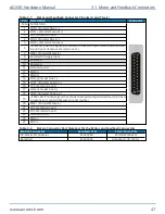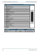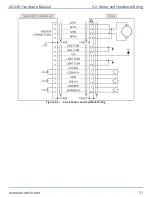
3.2. Motor and Feedback Wiring
DANGER
: To decrease the risk of electrical shock, injury, death, and damage to the
equipment, obey the precautions that follow.
l
Make sure that all components are grounded correctly and that they obey the local
electrical safety requirements.
l
It is the responsibilty of the system integrator or qualified installer to determine and
meet all safety and compliance requirements when they integrate the AGV3D into a
completed system.
l
Restrict access to the AGV3D when it is connected to a power source.
AGV3D scan heads are wired and assembled at the factory. Contact your Aerotech representative if you
have any questions on system configuration. For cable drawings, refer to the documentation that
shipped with your system.
Table 3-5:
Aerotech Motor and Feedback Cable Part Numbers
Aerotech Controller
Nmark GCL or Automation1 GL4
Cable Application
Standard
Hi-Flex
Interface Cable Part Number
C23680-xxx
(1,2)
C23690-xxx
(1,2)
(1) -xxx = Cable Length in Decimeters (1 Decimeter = 3.937 inches)
(2) Contact the factory for standard and custom length cables
AGV3D Hardware Manual
3.2. Motor and Feedback Wiring
www.aerotech.com
49
Summary of Contents for AGV3D Series
Page 1: ...Revision 2 00 AGV3D Three Axis Laser Scan Head HARDWARE MANUAL...
Page 6: ...This page intentionally left blank List of Tables AGV3D Hardware Manual 6 www aerotech com...
Page 12: ...This page intentionally left blank Laser Shutter AGV3D Hardware Manual 12 www aerotech com...
Page 16: ...Figure 1 2 Standard AGV3D Chapter 1 Overview AGV3D Hardware Manual 16 www aerotech com...


