2.8. Changing the Dynamic Focusing Field-of-View Setting
The AGV3D has two field of view options for the Z-axis: -F1 and -F2 (refer to
). The procedure
that follows explains how to change the field of view setting.
IMPORTANT
: The AGV3D must be set to either the -F1
or
the -F2 option. The AGV3D
cannot be set to a field of view between these two settings.
Make sure that the AGV3D is securely mounted and in an upright position and you can access the
bottom of the enclosure. The procedure cannot be done with the bottom mounting plate (-M2 option)
attached.
HOW TO CHANGE THE FIELD OF VIEW SETTING
WARNING
: Turn off the laser and disconnect the AGV3D from power before you start this
procedure.
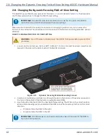
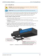
1. Loosen, but do not remove, the four [QTY. 4] M4x0.7, 14 mm LG socket head cap screws that are
located in the slots on the bottom side of the AGV3D enclosure.
Figure 2-9:
Dynamic Focusing Module Mounting Screws
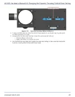
2. Insert a 6 mm allen key, or similar tool, through the slot in the bottom of the enclosure and into
the hole in the bottom of the Dynamic Focusing Module (DFM).
3. Use the tool to slide the DFM to the new field of view setting. The DFM is in the correct position
when a reference edge is encountered and the DFM cannot be moved any further in the correct
direction.
l
-F1 Option: Slide the DFM to the right
l
-F2 Option: Slide the DFM to the left
IMPORTANT
: The M4 screws do not need to reach the ends of their slots for the DFM to
be in the correct position.
2.8. Changing the Dynamic Focusing Field-of-View Setting AGV3D Hardware Manual
42
www.aerotech.com
Summary of Contents for AGV3D Series
Page 1: ...Revision 2 00 AGV3D Three Axis Laser Scan Head HARDWARE MANUAL...
Page 6: ...This page intentionally left blank List of Tables AGV3D Hardware Manual 6 www aerotech com...
Page 12: ...This page intentionally left blank Laser Shutter AGV3D Hardware Manual 12 www aerotech com...
Page 16: ...Figure 1 2 Standard AGV3D Chapter 1 Overview AGV3D Hardware Manual 16 www aerotech com...


