BM/BMS Series Hardware Manual
List of Tables
www.aerotech.com vii
LIST OF TABLES
Table 1-1:
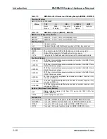
BM Motor Part Number and Ordering Example........................1-9
Table 1-2:
BM Motor Options .....................................................................1-9
Table 1-3:
BMS Motor Part Number and Ordering Example (BMS60
– BMS100) ..............................................................................1-10
Table 1-4:
BMS Motor Options (BMS60 – BMS100) ...............................1-10
Table 1-5:
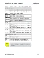
BMS Motor Part Number and Ordering Example
(BMS280 – BMS465) ..............................................................1-11
Table 1-6:
BMS Motor Options (BMS280 – BMS465) .............................1-11
Table 1-7:
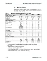
BM75, BM130, BM200 Motor Specifications (NEMA 23
Frame).....................................................................................1-12
Table 1-8:
BM250 and BM500 Motor Specifications (NEMA 34
Frame).....................................................................................1-13
Table 1-9:
BM800, BM1400 Motor Specifications (NEMA 42 Frame) .....1-14
Table 1-10:
BM2000, BM3400, BM4500 Motor Specifications (IEC
142 Frame)..............................................................................1-15
Table 1-11:
BMS60, BMS100 Motor Specifications (NEMA 23
Frame).....................................................................................1-16
Table 1-12:
BMS280, BMS465 Motor Specifications (NEMA 34
Frame).....................................................................................1-17
Table 1-13:
Encoder Specifications ...........................................................1-18
Table 1-14:
Resolver Specifications...........................................................1-18
Table 1-15:
Motor Power Connector Pin Assignment (MS3101A-
10P).........................................................................................1-19
Table 1-16:
Feedback Connector Pin Assignment (MS3101A-20-
29P).........................................................................................1-19
Table 1-17:
Resolver Connector Pin Assignment (MS3101A-20-29P)......1-19
Table 1-18:
D-sub Connector Pin Assignment...................
.
......................1-20
Table 1-19:
Preventative Maintenance ......................................................1-30
Table C-1:
Current Changes...................................................................... C-1
Table C-2:
Archived Changes.................................................................... C-2
∇
∇
∇
Summary of Contents for BM Series
Page 6: ...Table of Contents BM BMS Series Hardware Manual iv www aerotech com...
Page 8: ...List of Figures BM BMS Series Hardware Manual vi www aerotech com...
Page 10: ...List of Tables BM BMS Series Hardware Manual viii www aerotech com...
Page 12: ...Declaration of Conformity BM BMS Series Hardware Manual x www aerotech com...
Page 50: ...Appendix A BM BMS Series Hardware Manual A 8 www aerotech com...
Page 56: ...Index BM BMS Series Hardware Manual Index 2 www aerotech com...
Page 58: ......


