Set Up
DR500 Operation and Technical Manual
2-14
Aerotech, Inc.
Version 16
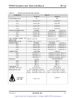
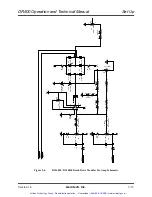
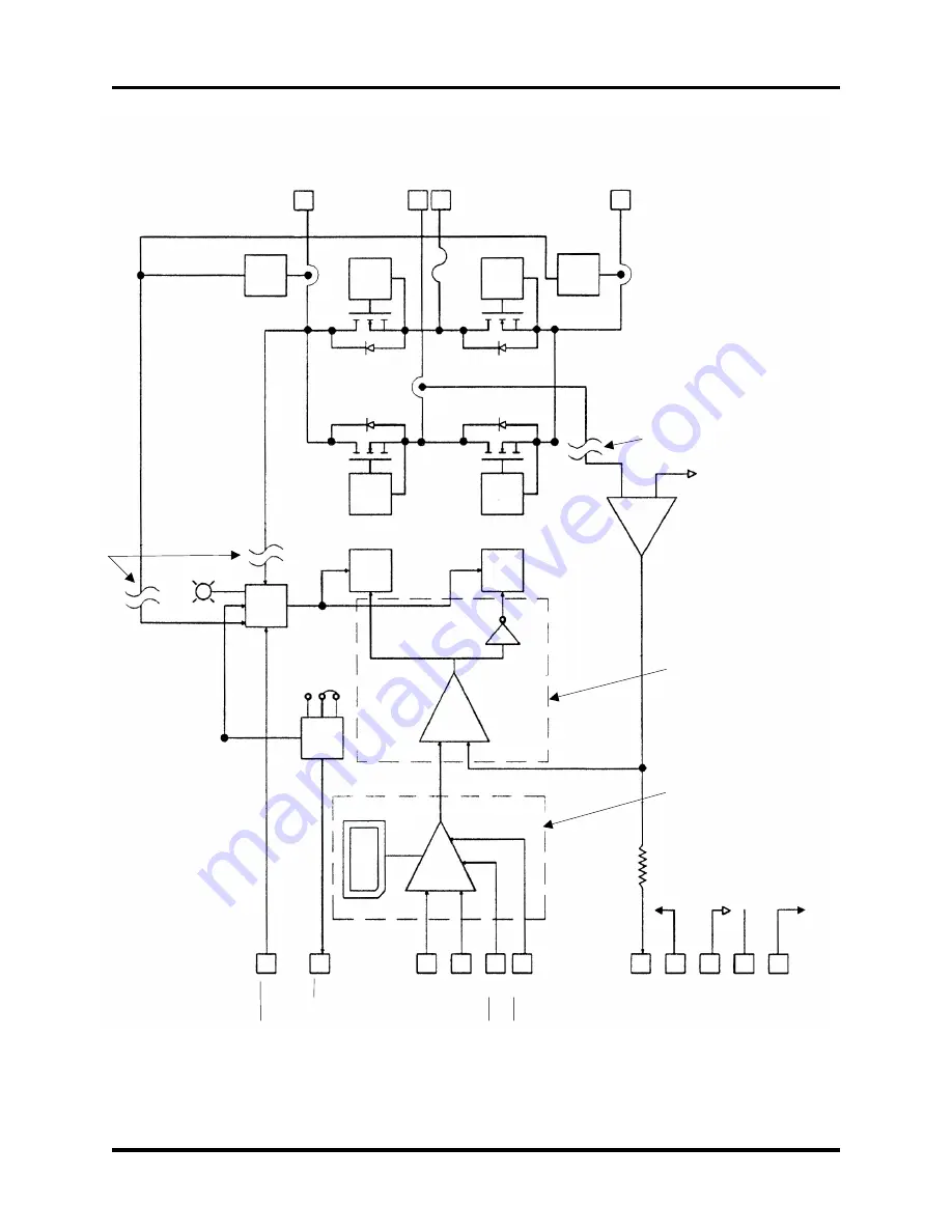
Figure 2-5.
Simplified Block Diagram of the DS160 Series Servo Amplifier Module
J1
S
hut
dow
n
6
J1
F
a
ult/
F
ault 10
J1
In
put *
16
J1
T
a
ch *
18
J1
I Lim
it +
12
I
Limit
–
14
J1
J1
Curr
ent
8
J1
+
12
20
J1
S
ig
C
om
24
J1
Heatsink
4
J1
–
12
22
Monit
o
r
Grou
nd
RCN4
Vc
o
m
Vf
b
–
–
5K
Ohm
s
+
1
2
HS
–12
–
+
Icom
Ifb
—
*
**
*
*
**
*
—
F
aul
t
Logi
c
*
**
JP
1
F
ault
3 Out
put
2
S
e
lec
t
1
Jumper
S
h
ut
Do
wn
Lo
gi
c
A
c
tive LE
D
Isol
ati
o
n
–
+
C
u
rr
ent
F.
B.
A
m
p
lifie
r
Dr
ive
r B *
*
Dr
ive
r A *
*
A
B
Re
ce
ive
r B
Re
ce
ive
r A
Isol
ati
o
n
H
igh B
us C
urr
ent Inhi
bi
t
Fl
oati
ng D
ri
v
ers a
nd R
ecei
v
er
s
H
igh B
u
s V
o
lt
age
Inhi
bi
t
P
o
wer
S
tage
Re
ce
ive
r A
Re
ce
ive
r B
Sh
o
rt
Cir
cu
it
S
e
nsor
J1
28 +
B
(
B
us)
J1
2
6
+
*
3
0
– M
o
tor
J1
J1
32
–B
(
R
etur
n)
C
onnecti
o
n
s
P
re
-Am
p
lifie
r (
De
ta
ils in
Fi
gur
es 2-6
and 2-
7)
Po
st-
A
m
p
lifie
r (
De
ta
ils
in
Fi
gur
e 2-
9)
*
Inpu
t/Outpu
t T
ransfer
Conventio
n (Op
en Lo
op)
A
pl
us (
+
) vol
ta
ge on
ei
ther i
n
put or
tach w
it
h
re
spect to si
g
nal
comm
on, pr
oduc
es a ne
t pl
us
(
+
)
v
ol
tag
e
on m
o
tor c
onnecti
o
n
26 w
it
h
re
spect to m
o
tor
connec
ti
on 30.
**
P
a
tent N
o
.
4, 554
, 512
on D
ri
v
er
/R
ecei
ver
A
an
d B
.
**
* C
o
n
nect
J
P
1
-1
to 2
for ac
ti
ve l
o
w
faul
t
output
.
C
onn
ect
J
P
1
-2
to 3
for ac
ti
ve hi
gh f
aul
t out
put.
N
O
T
E
: A
c
ti
ve hi
gh faul
t
output
must
not be
used w
it
h th
e D
R
S
e
ri
es m
o
ther
boar
d.
**
**
C
u
rr
ent C
o
m
m
a
nd (
Icom
)and c
u
rr
ent fee
dback
(
Ifb) g
a
ins for
amplifier
D
S
16030
–
5A
m
p / V
ol
t
D
S
16020
–
3A
m
p / V
ol
t
Artisan Technology Group - Quality Instrumentation ... Guaranteed | (888) 88-SOURCE | www.artisantg.com


