Set Up
DR500 Operation and Technical Manual
2-22
Aerotech, Inc.
Version 16
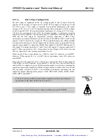
2.2.6. Stepper Drive Configuration (AM16007)
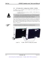
To configure a slot in the DR500 for a stepper drive module (Figure 2-10), proceed with
the following steps:
•
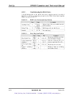
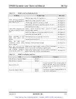
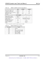
Set jumpers and drive key according to AM16007 Stepper Drive
Configuration Table 2-3.
To minimize the risk of electrical shock and bodily injury, ensure that all electrical
power switches are in the off position for 1 minute before inserting/removing drive
modules or changing jumper configurations.
To prevent another drive type from being inadvertently inserted into a slot configured for
another type drive module, the mating drive connector on the motherboard should have a
key (Aerotech part number EAM857 otherwise Schroff #21101-252) inserted into slot C.
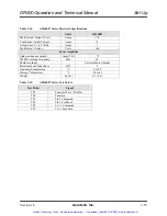
Refer to Figure 2-3. Electrical specifications and test points are listed in Table 2-14 and
Table 2-15, respectively.
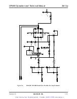
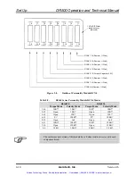
Figure 2-10.
AM16007 Stepper Drive Modules
WARNING
Artisan Technology Group - Quality Instrumentation ... Guaranteed | (888) 88-SOURCE | www.artisantg.com

