DR500 Operation and Technical Manual
Set Up
Version 1.6
Aerotech, Inc.
2-31
2.7. Electrical
Installation
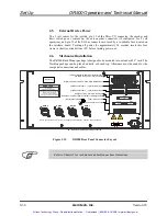
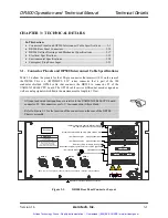
Motor, power, control, and position feedback cable connections are made to the rear of
the DR500 (refer to Figure 2-15). To make the external power connection, the AC line
cord (supplied with the DR500) is plugged into the lower right hand corner female plug.
Verify that the DR500 is configured for the correct AC line voltage.
The limit/encoder feedback connections connect to the appropriate axis, and the motor
drive connections connect to the matching motor connector. For example, the location for
the axis 1 motor connector is behind the axis 1 drive module (i.e., the axis motor
connectors on the rear of the chassis are numbered 4 through 1 from left to right). Control
connections are made through connector J1, labeled “From U500/U600 P1”.
When using an AC brushless motor or the I/O bus, use the optional DIOSR/DRC cable
that connects to P5 of the U500 or P10 of the U600 and to the rear of the DR500 to
connector J10 (labeled “From UNIDEX 500-P5/U600-P10”). This cable accommodates
Hall effect feedback devices. For applications that require resolver or inductosyn
feedback, connect these cables directly to the resolver option board within the personal
computer. When using the optional joystick or brake functions, the joystick connection is
made at connector J12 (labeled “JOYSTICK”) and the Brake connection is made at
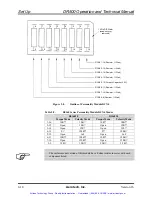
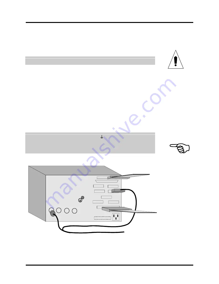
connector J14 (labeled “BRAKE”). Refer to Figure 2-16 for an example of the electrical
connections made on the rear of the DR500.
Protective grounding (indicated by the symbol “ ”) is through the main power
connection.
The supply connection is the main power cord (the main power disconnect).
Figure 2-16.
DR500 Electrical Connections
WARNING
AXIS 4 AXIS 3 AXIS 2 AXIS 1
FROM UNIDEX 500 P5
I/O BUS / OPTO22
AXIS 1 J2 AXIS 2
AXIS 3 AXIS 4
MISC. I/O
JOYSTICK BRAKE
FROM UNIDEX 500 P1
AC TAG
Artisan Technology Group - Quality Instrumentation ... Guaranteed | (888) 88-SOURCE | www.artisantg.com

