DR500 Operation and Technical Manual
Technical Details
Version 1.6
Aerotech, Inc.
3-11
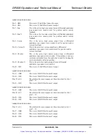
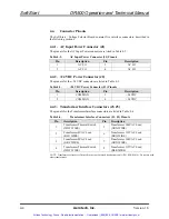
3.2.2. Joystick Connector
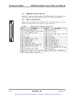
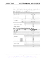
Table 3-3 shows the pinouts for the Joystick connector. The mating connector is a Cinch
# DA-15P (Aerotech # ECK100).
Table 3-3.
Pinouts for the Joystick Interface Connector (J12)
Pin #
Description
Pin #
Description
1
+5 Volts
9
2
Joystick Button A/C Input
10
3
Joystick Potentiometer 1 Input
11
4
Common
12
5
13
Joystick Interlock (common) Input
6
Joystick Potentiometer 2 Input
14
7
Joystick Button B/C Input
15
8
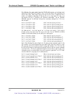
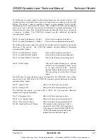
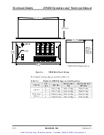
Figure 3-4.
Joystick Interface
8
15
9
1
Joy X
Joy Y
Button A
Button B
Joy Interlock
Common
+5V
Com
+5V
Com
100
(Typ. 2 plc’s)
B A C
Speed Select
Buttons
(all N.O.)
Axis Pair Select
Exit Slew Mode
IN914
Button B
Button C
Button A
Arrows below show
axes motion that results
when joystick is used.
+Y
-X +X
-Y
Artisan Technology Group - Quality Instrumentation ... Guaranteed | (888) 88-SOURCE | www.artisantg.com


