Technical Details
DR500 Operation and Technical Manual
3-16
Aerotech, Inc.
Version
1.6
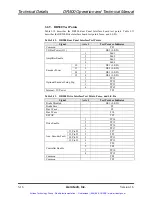
3.2.9. DR500 Test Points
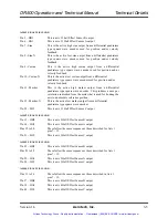
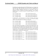
Table 3-12 describes the DR500 Rear Panel Interface board test points. Table 3-13
describes the DR500 Drive Interface board test points, fuses, and L.E.Ds.
Table 3-12. DR500 Rear Panel InterfaceTest Points
Signal
Axis #
Test Point or Indicator
Common
TP1
I/O Bus Power (J11)
DS5 (L.E.D.)
1 Pad
1
2 Pad
2
3 Pad
3
Amplifier Enable
4 Pad
4
J2 1
DS1
(L.E.D.)
J3 2
DS2
(L.E.D.)
J4 3
DS3
(L.E.D.)
Encoder Power
J5 4
DS4
(L.E.D.)
1 TP12
2 TP22
3 TP32
Optional Encoder Setup Sig.
4 TP42
In5V Power
TP2
Table 3-13. DR500 Drive InterfaceTest Points, Fuses, and L.E.D.s
Signal
Axis #
Test Point or Indicator
Brake Disabled
DS1 (L.E.D.)
Brake
Fuse
F9
Bus 1 Fuse
F8
Bus 2 Fuse
F10
ESTOP
TP5
1 TP14
2 TP15
3 TP16
Drive Enable
4 TP17
J2, Pin 23
1
TP7
J3, Pin 23
2
TP9
J4, Pin 23
3
TP11
Aux. Encoder Fault
J5, Pin 23
4
TP13
1 TP6
2 TP8
3 TP10
Controller Enable
4 TP12
Common
TP4
Common
TP3
Artisan Technology Group - Quality Instrumentation ... Guaranteed | (888) 88-SOURCE | www.artisantg.com


