
Electrical Specifications and Installation
ECO165LM Hardware Manual
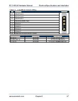
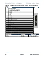
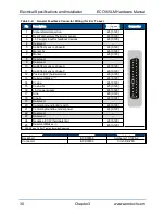
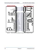
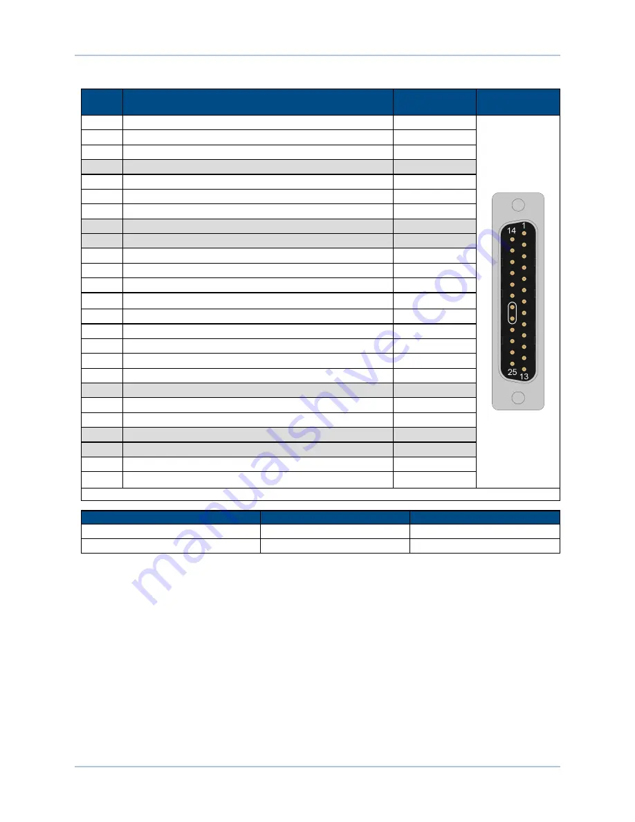
Table 3-4:
General Feedback Connector Wiring (for Z or T axes)
Pin
Description
Wire Gauge
AWG [mm
2
]
Connector
1
Signal shield connection
26 [0.129]
2
Over-Temperature Thermistor sensor
26 [0.129]
3
+5 V supply input for feedback devices
26 [0.129]
4
Reserved
--
5
Hall Effect sensor, phase B
26 [0.129]
6
Marker-N
26 [0.129]
7
Marker
26 [0.129]
8
Reserved
--
9
Reserved
--
10
Hall Effect sensor, phase A
26 [0.129]
11
Hall Effect sensor, phase C
26 [0.129]
12
Positive (CW) hardware limit
26 [0.129]
13
Reserved/Brake -
(1)
26 [0.129]
14
Cosine
26 [0.129]
15
Cosine-N
26 [0.129]
16
+5 V power supply
26 [0.129]
17
Sine
26 [0.129]
18
Sine-N
26 [0.129]
19
Reserved
--
20
Common ground to limit switch
26 [0.129]
21
Common ground to encoder power
26 [0.129]
22
Reserved
--
23
Reserved
--
24
Negative (CCW) hardware limit
26 [0.129]
25
Reserved/Brake +
(1)
26 [0.129]
1. BRAKE pins On Z or T axis, otherwise Reserved
Mating Connector
Aerotech P/N
Third Party P/N
Backshell
ECK00656
Amphenol 17-1726-2
Connector
ECK00300
Cinch DB-25S
30
Chapter 3
www.aerotech.com


