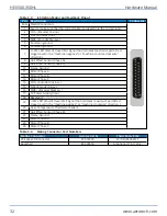
Table 3-3:
-E3 Option Motor and Feedback Pinout
Pin
Description
Connector
Case Shield Connection
1
Key (to make sure that the correct cable is plugged into the correct jack)
2
COS- (Encoder Cosine-)
3
SIN- (Encoder Sine-)
4
MRK- (Encoder Marker-)
5
Common ground
6
Common ground
7
-/CCW LMT (End-of travel limit signal that indicates maximum permitted
stage travel in the “machine negative” or “machine counter-clockwise”
direction.)
8
Hall Effect Sensor (Phase A)
9
Hall Effect Sensor (Phase C)
10
Frame Ground
11
Motor Phase A
12
Motor Phase B
13
Motor Phase C
14
COS+ (Encoder )
15
SIN+ (Encoder Sine+)
16
MRK+ (Encoder )
17
5V Power Supply Input
18
Reserved
19
+/CW LMT (End-of travel limit signal that indicates maximum permitted
stage travel in the “machine positive” or “machine clockwise” direction.)
20
Over-Temperature Thermistor Sensor
21
Hall Effect Sensor (Phase B)
22
Frame Ground
23
Motor Phase A
24
Motor Phase B
25
Motor Phase C
Table 3-4:
Mating Connector Part Numbers
Mating Connector
Aerotech P/N
Third Party P/N
25-Socket D-Connector
ECK00300
FCI DB25S064TLF
Backshell
ECK00656
Amphenol 17E-1726-2
HEX500-350HL
Hardware Manual
32
www.aerotech.com
Summary of Contents for HexGen HEX500-350HL
Page 1: ...Revision 2 01 HexGen HEX500 350HL Hexapod Six DOF Positioning System HARDWARE MANUAL...
Page 16: ...This page intentionally left blank HEX500 350HL Hardware Manual 16 www aerotech com...
Page 22: ...This page intentionally left blank HEX500 350HL Hardware Manual 22 www aerotech com...
Page 40: ...This page intentionally left blank HEX500 350HL Hardware Manual 40 www aerotech com...
Page 44: ...This page intentionally left blank HEX500 350HL Hardware Manual 44 www aerotech com...
Page 48: ...This page intentionally left blank HEX500 350HL Hardware Manual 48 www aerotech com...

