Ndrive FCL Hardware Manual
Installation and Configuration
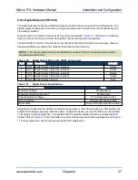
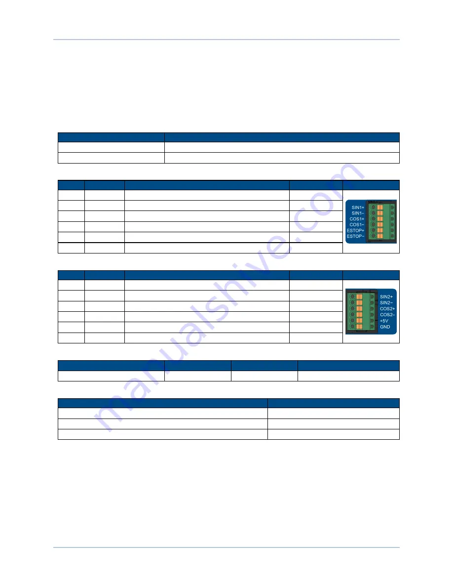
2.6. Encoder Input (TB103 A/B)
The Ndrive FCL is equipped with two auxiliary encoder input channels that are accessible through
TB103A/B. The encoder interfaces accept an RS-422 differential line driver.
The auxiliary encoder input channels cannot be used for closing the position loop. They are intended to be
used with the Infinite Field of View and the Marking on the Fly functionality of the Ndrive FCL.
Table 2-15:
Encoder Input Specifications (TB103)
Specification
Value
Encoder Frequency
10 MHz maximum (25 nsec minimum edge separation)
x4 Quadrature Decoding
40 million counts/sec
Table 2-16:
Encoder Input Connector Pinout (TB103 A)
Pin
Label
Description
In/Out/Bi
Connector
1
SIN1+
Encoder SIN+ Input
Input
2
SIN1-
Encoder SIN- Input
Input
3
COS1+
Encoder COS+ Input
Input
4
COS1-
Encoder COS- Input
Input
5
ESTOP+
Emergency Stop Digital Input +
Input
6
ESTOP-
Emergency Stop Digital Input -
Input
Table 2-17:
Encoder Input Connector Pinout (TB103 B)
Pin
Label
Description
In/Out/Bi
Connector
1
--
Reserved
Input
2
--
Reserved
Input
3
--
Reserved
Input
4
--
Reserved
Input
5
+5V
+5V Encoder Power
Output
6
GND
Ground
--
Table 2-18:
6-Pin Terminal Block Mating Connector Specifications for TB103 A/B
Type
Aerotech P/N
Phoenix P/N
Wire Size: mm
2
[AWG]
6-Pin Terminal Block
ECK02220
1881367
0.5 - 0.080 [20-28]
Table 2-19:
Cable Part Numbers
Drive Type
Cable P/N
Ndrive CP, HPe, or HLe
C25481-xx
Ndrive MP
C25483-xx
Npaq
C25482-xx
www.aerotech.com
Chapter 2
29


