Npaq MR Hardware Manual
Installation and Configuration
2.2. Electrical Installation
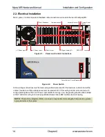
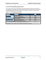
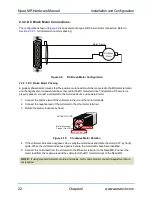
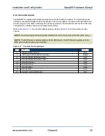
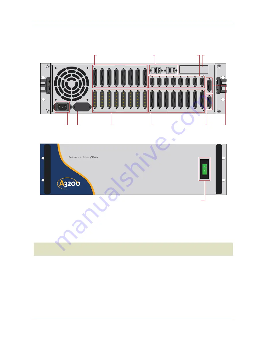
Motor, power, control and position feedback cable connections are made to the rear of the Npaq MR.
FEEDBACK
COMMUNICATIONS
1
2
3
4
5
6
7
8
1
2
3
4
5
6
7
8
1
2
3
4
5
6
7
8
1
2
3
4
5
6
7
8
EXT DRIVE
RS232
AUX ENCODER
JOYSTICK
ESTOP
MOTOR
DIGITAL / ANALOG IO
Motor Output
AC Power Input
AC Power Label
Digital / Analog IO
Motor Feedback
Auxiliary Encoder
ESTOP
Joystick
Communications
System Serial
Label
Figure 2-1:
Power and Control Connections
AEROTECH.
COM
ON
OFF
Npaq MR
Power Switch / Circuit Breaker
Figure 2-2:
Power Switch
All low voltage connections must be made using cables/wires sized for the maximum currents that will be
carried. Insulation on these cables/wires must be rated at 300 V if this wiring can come into contact with
wiring operating above 100 V (AC Power Input and Motor wiring). Low voltage wiring should not be bundled
with AC and motor wiring to minimize signal disturbances due to EMI interference and coupling.
N O T E :
The machine integrator, OEM, or end user is responsible for meeting the final protective ground-
ing requirements of the system.
14
Chapter 2
www.aerotech.com


