Npaq MR Hardware Manual
Installation and Configuration
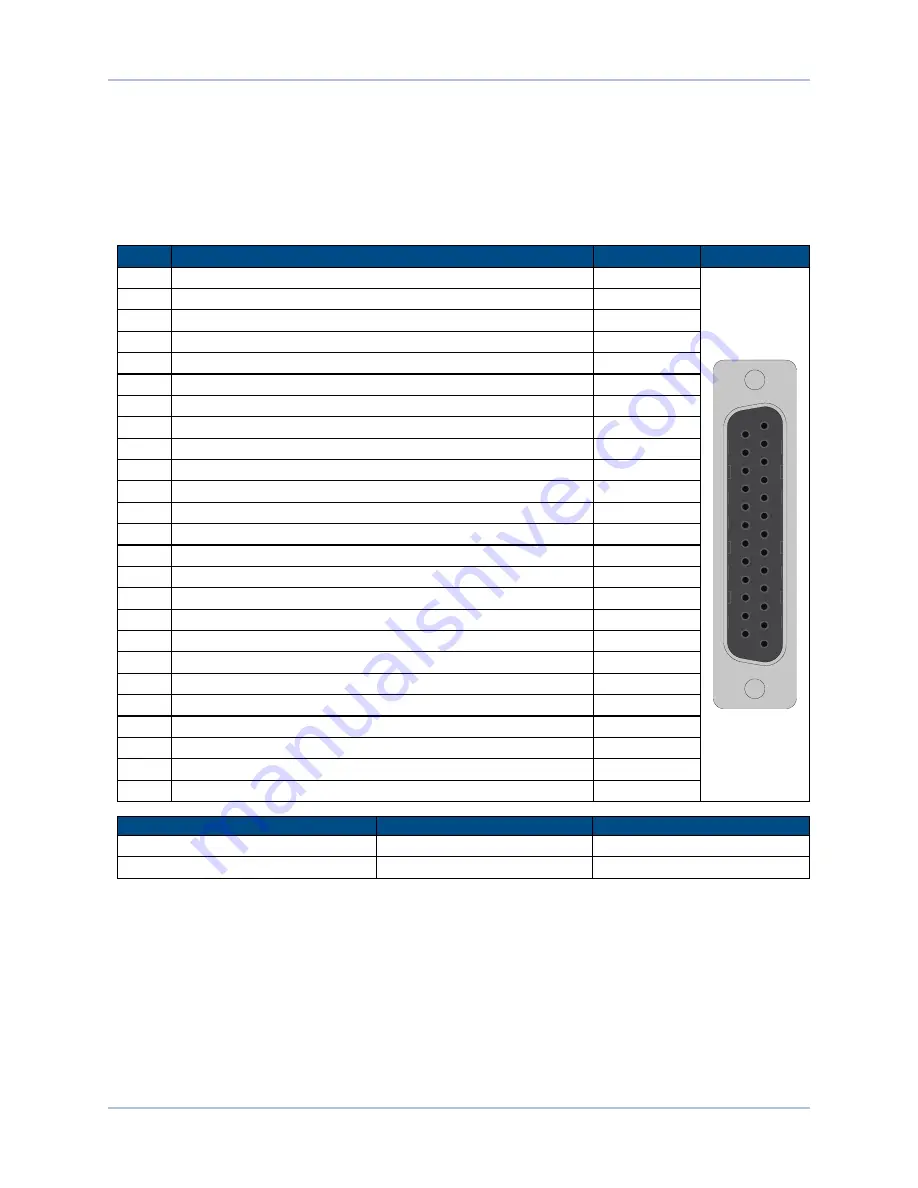
2.5. Digital / Analog IO Connections
The IO connections includes 8 digital opto-inputs, 8 digital opto-outputs, 1 analog input, 1 analog output, a
second encoder channel, and a brake/relay output. This connector is installed only if the -IO option has been
ordered for the axis.
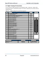
Table 2-19:
Digital / Analog IO Connector Pin Assignment
Pin#
Description
In/Out/Bi
Connector
1
Non-Inverting Analog Input 1+
Input
13
25
1
14
2
InvertingAnalog Input 1-
Input
3
In5 Volt Power Supply (500 mA max)
Output
4
Input Common for Opto-Inputs 0 - 3
Input
5
Optically-Isolated Input 0
Input
6
Optically-Isolated Input 1
Input
7
Optically-Isolated Input 2
Input
8
Optically-Isolated Input 3
Input
9
Output
Input
10
Optically-Isolated Output 0
Output
11
Optically-Isolated Output 1
Output
12
Optically-Isolated Output 2
Output
13
Optically-Isolated Output 3
Output
14
Analog Output 1
Output
15
Ground
N/A
16
Input Common for Opto-Inputs 4 - 7
Input
17
Optically-Isolated Input 4
Input
18
Optically-Isolated Input 5
Input
19
Optically-Isolated Input 6
Input
20
Optically-Isolated Input 7
Input
21
Output Common -
Input
22
Optically-Isolated Output 4
Output
23
Optically-Isolated Output 5
Output
24
Optically-Isolated Output 6
Output
25
Optically-Isolated Output 7
Output
Mating Connector
Aerotech P/N
Third Party P/N
25-Pin D-Connector
ECK00101
FCI DB25P064TXLF
Backshell
ECK00656
Amphenol 17E-1726-2
38
Chapter 2
www.aerotech.com


