background image

50 - 88

MCH-6

C

A

b

e

A C

g

h

A C

A C

A C

A C

A

C

C

A

A

C

c

d

f

e

f

a

b

c

d

a

A

1

2

i

i

ENGLISH

РУССКИЙ

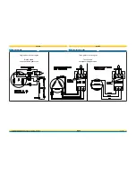
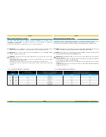
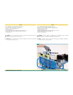
To refill bottles with standard connectors (1):

- Fit the hose connector (g) to the bottle valve (b).

- Screw in the fixing knob (h) until it is completely tightened.

- Start the compressor.

- Open the valve (e) by rotating it anticlockwise.

- When the refill has been completed shut the compressor down.

- Close the valve (e) by rotating it clockwise.

- Open the condensate drain valves (i) (see “7.10 Condensate discharge”) until all the residual air in the

  compressor has been expelled.

- Unscrew the fixing knob (h) by rotating it anticlockwise.

- Disconnect the bottle coupling.

To refill bottles with BC connectors (2):

- Fit the hose connector (a) to the bottle valve (b).
- Screw in the fixing knob (c) until it is completely tightened.
- Check that the bleed valve (f) is closed by rotating it clockwise.
- Open the valve (d) by rotating it anticlockwise.
- Start the compressor.
- Open the valve (e) by rotating it anticlockwise.
- When the refill has been completed shut the compressor down.
- Close valves (d) and (e) by rotating them clockwise.
- Open the bleed valve (f) by rotating it anticlockwise until all the residual air in the fitting has been
  expelled.
- Unscrew the fixing knob (c) by rotating it anticlockwise.
- Disconnect the bottle coupling.

При заправке баллонов со стандартным коннектором

 (1):

- Соедините коннектор шланга (g) вентилем баллона (b).

- Закрутите гайку коннектора (h) до упора.

- Запустите компрессор.

- Откройте вентиль (e), вращая его против часовой стрелки.

- После окончания заправки отключите компрессор.

- Закройте вентиль (e), вращая его по часовой стрелке.

- Откройте вентили сброса конденсата (i) (см. раздел “7.10 Удаление конденсата”) до полного сброса

  избыточного давления.

- Открутите гайку коннектора (h), вращая ее против часовой стрелки.

- Отсоедините баллон.

При заправке баллонов с

 BC-

коннектором 

(2):

- Соедините коннектор шланга (a) вентилем баллона (b).
- Закрутите гайку коннектора (c) до упора.
- Проверьте, что клапан сброса давления (f) закрыт, повернув его по часовой стрелке.
- Откройте вентиль (d), вращая его против часовой стрелки.
- Запустите компрессор.
- Откройте вентиль (e), вращая его против часовой стрелки.
- После окончания заправки отключите компрессор.
- Закройте вентили (d) и (e), вращая их по часовой стрелке.
- Откройте вентиль сброса (f), вращая его против часовой стрелки до полного сброса избыточного
  давления.
- Открутите гайку коннектора (c), вращая ее против часовой стрелки.
- Отсоедините баллон.

Summary of Contents for MCH-6/EM COMPACT

Page 1: ...C000120 N SC000121 N SC000122 N SC000120 I SC000121 I SC000122 I SC000120 COMP SC000121 COMP SC000122 COMP SC000120 COMP I SC0000121 COMP I SC000122 COMP I SC000130 R SC000131 R SC000132 R SC000133 R...

Page 2: ......

Page 3: ...mation provided on the following pages Ensure that the manual is at the disposal of the personnel who will be using managing the compressor and carrying out any maintenance on it Should you require an...

Page 4: ...ation null and void Should unscheduled maintenance work or spare parts must be required always contact the manufacturer The user s instruction manual is an integral part of the machine a full understa...

Page 5: ...nside the filter see chap 7 12 For compressors with combustion engines Check fuel level and top up if necessary see section 7 7 For compressors with electric motors Connect the electric motor to the m...

Page 6: ...upling 1 from the bottle A Maintenance After the first 5 working hours change the oil again see section 7 6 3 Check the lubricating oil level every 5 hours see section 7 6 2 Change the lubricating oil...

Page 7: ...1 4 Checks and maintenance 3 1 4 20 3 2 General precautions 3 2 21 3 2 1 Important safety information 3 2 1 23 3 2 2 Accident prevention 3 2 2 23 3 2 3 Working safety 3 2 3 23 3 2 4 Noise level 3 2 4...

Page 8: ...44 6 2 2 Checking that the flex hoses are in good condition 6 2 2 44 6 2 3 Fuel level check 6 2 3 45 6 2 4 Storing technical documentation 6 2 4 45 6 3 Preliminary tasks 6 3 46 6 3 1 Checking the safe...

Page 9: ...ssistance service 10 2 Scheduled maintenance 10 3 Using the compressor under heavy duty conditions 10 4 The Customer Care Centre 10 5 Scheduled maintenance registry coupons 10 1 10 2 10 3 10 4 10 5 66...

Page 10: ...t This manual must be read carefully All compressor operators maintenance personnel must read this entire manual with due care and attention and observe the instructions information contained herein C...

Page 11: ...nt of resale keep the manual in good condition and ensure its contents remain undamaged do not remove tear or re write any part of the manual for any reason keep the manual protected from damp and hea...

Page 12: ...with due care and attention constant and careful preventive maintenance will always ensure a high level of safety when using the compressor Never postpone repairs and have them carried out by special...

Page 13: ...f charge by AEROTECNICA COLTRI SpA at its plant in San Martino della Battaglia BRESCIA costs regarding transport delivery of spare parts and any materials subject to wear shall be met by the customer...

Page 14: ...r he she must demonstrate that the damage has been a major and direct consequence of this defect AEROTECNICA COLTRI SpA AEROTECNICA COLTRI The compressors mod MCH 6 have been designed and built for th...

Page 15: ...ure the lead is not bent at a sharp angle and that it does not rub against any sharp edges Use of extensions is not recommended Never run the compressor when the power lead is damaged there is evident...

Page 16: ...nual especially as safety guards and safety symbols are concerned It is also forbidden to carry out work in any way other than that described or to neglect the illustrated safety tasks The safety info...

Page 17: ...10 Each compressor is carefully run and tested prior to delivery A new compressor must nevertheless be used with caution during the first 5 working hours so as to complete proper running in of its co...

Page 18: ...cess gases Nitrogen Helium Nitrox 40 max O2 40 Each compressor has an identification label a attached to its frame a WARNING This manual must be read carefully before transporting installing using or...

Page 19: ...bserve national safety regulations Do not remove or damage guards labels or notices especially those required by law The adhesives attached to the compressor are there for safety purposes They must be...

Page 20: ...eye goggles accident prevention shoes and ear defenders against noise Make sure a first aid cabinet and a CO2 fire extinguisher are near the compressor Keep the extinguisher fully loaded Use accordin...

Page 21: ...erfect understanding of how the compressor works know how to use the controls and have read the technical information contained in this manual WARNING It is forbidden to tamper with or replace compres...

Page 22: ...efore leaving the machine unattended place a sign on the compressor indicating that maintenance work is in progress and that it must not be restarted Never place hands or introduce screwdrivers keys o...

Page 23: ...ressure compressors The compressor has been designed for use in weather conditions as refer to 1 9 Where the machine may be used 1 9 The manufacturer cannot be held liable for malfunction or damage if...

Page 24: ...ed 2 Electrical dangers Use the machine with suitable insulation especially against water and humidity 3 Dangers derived from use of internal combustion engine Observe instruction in the relevant engi...

Page 25: ...25 88 MCH 6 4 8 7 2 7 1 3 6 5 5 ENGLISH 3 3 SAFETY INFO LABELS LOCATION 3 3...

Page 26: ...phone must be worn e Forbidden to remove covers guards f Forbidden to lubricate mechanical parts when they are moving compressor must be switched off before any maintenance lubrications tasks are carr...

Page 27: ...nfo plate Check lubricating oil level every 5 working hours and change it every 50 working hours For information on how to check see 7 6 2 Checking the oil level For information on how to change the o...

Page 28: ...eck that a fire extinguisher is present Make sure all personnel know where it is Periodically check that extinguishers are full and operators know how to use them The location of the first aid cabinet...

Page 29: ...ance tasks described in this manual must only be carried out by trained authorised personnel For component maintenance revision tasks not covered by this manual please contact AEROTECNICA COLTRI 3 5 3...

Page 30: ...sh lubrication occurs by oil thrower pin screwed onto the 2nd stage connecting rod Fourth stage lubrication is of the oil vapour type 4 1 4 4 1 4 Lubrication The cooling pipes are made of stainless st...

Page 31: ...ternal combustion engine exhaust pipe 18 Safety valve 19 Condensate discharge 20 Condensate separator 1 2 3 4 5 6 7 8 9 10 4 3 TECHNICAL CHARACTERISTICS 4 3 IMPORTANT For the MCH 6 EM models If the co...

Page 32: ...8 giri min rpm 3600 3600 3600 3600 giri min rpm 2800 2800 2800 2800 Engine rpm Pumpin Unit Working pressure bar 225 300 330 225 300 330 225 300 330 225 300 330 PSI 3200 4300 4700 3200 4300 4700 3200 4...

Page 33: ...2 4 2 Hp 5 6 5 6 giri min rpm 4000 4000 giri min rpm 2800 2800 Engine rpm Pumpin Unit Working pressure bar 225 300 330 225 300 330 PSI 3200 4300 4700 3200 4300 4700 Delivery rate l min 100 100 m3 h 6...

Page 34: ...15 230 230 115 230 230 Hz 50 60 60 50 60 60 50 60 60 50 A 14 29 14 14 29 14 14 29 14 28 Engine rpm Voltage Frequency Absorption Pumpin Unit giri min rpm 2250 2250 2250 2800 Working pressure bar 225 30...

Page 35: ...z 50 50 60 60 50 50 60 60 50 50 60 60 A 11 5 6 7 11 5 6 7 11 5 6 7 11 5 6 7 11 5 6 7 11 5 6 7 Engine rpm Voltage Frequency Absorption Pumpin Unit giri min rpm 2800 2800 2800 Working pressure bar 225 3...

Page 36: ...e 1st stage 3 Outlet valve 1st stage 4 Cooling pipe 1st 2nd stage 5 Outlet valve 2nd stage 6 Cooling pipe 2nd 3rd stage 7 Outlet valve 3rd stage 8 Cooling pipe 3rd 4th stage 9 Outlet valve 4th stage 1...

Page 37: ...37 88 MCH 6 ENGLISH 4 5 WIRING DIAGRAM 4 5 Single phase electric engine Three phase electric engine...

Page 38: ...itres 1 active carbon and molecular sieve filte cartrige 1200 1 0 5 7 13 7 6 7 12 5 HANDLING AND INSTALLATION WARNING The compressors are delivered without the refill hoses compressor lubricating oil...

Page 39: ...sported to the designated placement area Transfer will require the use of a fork lift or transpallet of suitable load bearing capacity To lift the compressor use the carry handles a If the compressor...

Page 40: ...e necessary Position the compressor no closer than 1 m to surrounding walls the gap between compressor and ceiling should be at least 1 5 m These distances ensure proper compressor operation and prope...

Page 41: ...rom outdoors or a place with the cited ventilation requisites The extension supplied as an optional must be connected to the intake connector Remove the intake filter a Attach the fitting b Connect th...

Page 42: ...s supplied with an electrical lead To connect up to the power supply just insert the plug in the mains power socket Check that the data on the compressor ID plate is compatible with mains power supply...

Page 43: ...undamaged use and maintenance manual At the time of delivery the compressor has no active carbon molecular sieve filter cartridge fitted the cartridge is supplied together with the compressor in a se...

Page 44: ...efill flex hoses are in good condition 6 2 2 6 2 CHECKS TO BE RUN AT THE START OF EACH WORKING DAY 6 2 Inspect the exterior of the compressor couplings pipes pneumatic components etc and check for any...

Page 45: ...check A 6 2 3 A DANGER When topping up the fuel level make sure you do not spill any fuel as this could cause a fire If fuel is spilt it must be wiped up immediately The fuel is flammable therefore n...

Page 46: ...n al corrosion do not refill them even if they have been tested 6 3 PRELIMINARY TASKS 6 3 6 3 1 Checking the safety valves Check that safety valve is working properly by starting the compressor with t...

Page 47: ...imum position turn the shutdown switch to the ON position gently pull the starter handle d until the cord is taut then tug it sharply re accompany the handle gently back to its original position to pr...

Page 48: ...harge c points to prevent a strained start Check the voltage and that there is a proper earth contact connect the compressor up to the mains power supply press the start pushbutton a ON position close...

Page 49: ...se not involved in the refill procedure must maintain a safety distance of at least 3 metres Also it is forbidden to disconnect the hoses from the fittings or the fill valve while the machine is under...

Page 50: ...the fixing knob h by rotating it anticlockwise Disconnect the bottle coupling To refill bottles with BC connectors 2 Fit the hose connector a to the bottle valve b Screw in the fixing knob c until it...

Page 51: ...maintenance tasks run checks and or controls on the compressor switch off the compressor remove the plug from the mains socket The residual pressure present in the compressor pumping circuit must be...

Page 52: ...5 10 25 50 100 250 500 1000 1500 2000 3000 4000 1 2 3 4 5 Maintenance Intake filter Lubricating oil Main functions check Belt wear and tension Cleaning the separator filter element 1st 2nd 3rd stage...

Page 53: ...iston worn 4 Contact technical assistance Fittings loose leaking seals Check for leaks with soapy water and eliminate them Intake filter clogged Replace Intake extension kinked Straighten use stiffer...

Page 54: ...ter are classified as special wastes and must therefore be disposed of in compliance with the anti pollution laws in force All maintenance work must be carried out with the compressor OFF and the powe...

Page 55: ...ax a c 7 6 3 Changing the lubricating oil A The lubricating oil must be changed after the first 5 working hours running in then every 50 working hours or annually Every time the lubricating oil is cha...

Page 56: ...o not use materials than can generate sparks Use protective gloves when topping up the fuel level Always make sure the fire extinguisher is at hand when topping up the fuel level 7 7 CHECKING FUEL LEV...

Page 57: ...pressor OFF and the power supply lead unplugged from the mains socket 7 8 CHANGING THE INTAKE FILTER A 7 8 A After putting the compressor into service the intake filter must be changed after the first...

Page 58: ...rryoutthesetasksifthecompressorhas only ju st shut down wait for the compressor to cool All maintenance work must be carried out with the compressor OFF and the power supply lead unplugged from the ma...

Page 59: ...rking hours of the compressor To check belt tension remove the cover a by removing the fixing screws b and exert a pressure of approximately 10 Kg on the belt c check that the belt does not flex by mo...

Page 60: ...maintenance tasks To depressurise the entire compressor circuit proceed as follows in the section Condensate discharge 7 12 ACTIVE CARBON FILTER MOLECULAR SIEVE 7 12 The active carbon filter must be r...

Page 61: ...be disposed of in compliance with the anti pollution standards in force To change the active carbon filters b proceed as follows vent all the compressed air inside the circuit unscrew the filter cap a...

Page 62: ...efilling the tanks check that the hoses are perfectly connected and in good condition Check also that the valves on any unused hoses are closed properly so as to prevent the dangers that derive from h...

Page 63: ...nterior of the compressor Stop the compressor and refit the air intake filter Clean the external parts eliminate any moisture salt or oil deposits Protect the compressor from dust and water by storing...

Page 64: ...ful waste must be collected by authorised companies It is especially important that exhausted oils be disposed of in compliance with the laws in the country of use IMPORTANT At every stage of demoliti...

Page 65: ...h which to request assistance and register completed scheduled maintenance work Start up and maintenance checks tasks once completed by our qualified technician are registered in this maintenance chap...

Page 66: ...e technician ssignature Assistance servicestamp Typeofworkandnotes Date Maintenance technician ssignature Assistance servicestamp Typeofworkandnotes Date Maintenance technician ssignature Assistance s...

Page 67: ...ure Assistance servicestamp Typeofworkandnotes Date Maintenance technician ssignature Assistance servicestamp Typeofworkandnotes Date Maintenance technician ssignature Assistance servicestamp Typeofwo...

Page 68: ...lly dismantled If the machine should change ownership the manual must be passed on to the new owner Art 6 If the manual supplied should be lost or damaged a request for a copy should be sent to the ma...

Page 69: ...ed staff D The term Qualified Staff refers to members of staff who are familiar with the methods of installation assembly repair and operation of the machine and who have a specific technical qualific...

Page 70: ...the instruction manual when failure to comply with the regulations or tampering with the parts may cause serious injury to people permanent disablement or even death Caution E The heading is used in t...

Page 71: ...rovided with an earthing in order Art 15 D It is strictly forbidden to piace combustible material near the machine Art 16 It is strictly forbidden to intervene on any part of the machine unless it has...

Page 72: ...k left over grease or scraps must be disposed of according to specific national regulations through authorized disposal companies Oil and grease must not be discharged into drainpipes or drainholes Ar...

Page 73: ...blems that may arise during operation may only be looked into if the operators are not put under any danger Art 30 C Any staff authorized to approach the machines when in operation must wear suitable...

Page 74: ...58 CEE and 92 57 CE The employer is required to comply with these directives and to make sure they are followed by his workers Art 38 C During the machine operation and maintenance it is essential to...

Page 75: ...rators maintenance staff and any members of staff likely to operate and or pass near by the machine must be careful of the risks of catching clothes and or long hair in the moving parts Long hair shou...

Page 76: ...Art 52 C Crates and packs supplied with the machine may be lifted by hand if they weigh less than approx 30 Kg 49 A 50 B 51 52 C 30 11 4 DELIVERY REGULATIONS 11 4 Art 53 D When the machine is deliver...

Page 77: ...and their components must be moved using suitabemeans and equipment appropriate for this purpose Art 62 Do not empty the cylinders or the filters completely even during winter storage This will preven...

Page 78: ...rary removal was necessary have been resolved Art 68 If any digging has to be done or if the passages near the machines have to be blocked suitable means of protection and notices must be provided Art...

Page 79: ...prohibited to carry out any repair or adjustment operation on moving parts The operations must be carried out with the machine turned off Consequently the main power supply switch must be turned off a...

Page 80: ...ying out any maintenance work B 11 6 1 a b A c d 30 B 11 6 2 Purpose of the compressor Art 77 The compressor has been designed to obtain the highest quality breatheable air which is taken from the sur...

Page 81: ...ing the compressor to run idle for a few seconds with the drain valve turned on Art 84 Make sure that the minimum radius of curvature of the hose is not less than 250 mm Art 85 Particular care must be...

Page 82: ...recipients that contain or have contained inflammable liquids for example tanks of petrol or diesel fuelled compressors In case of doubt do not proceed with the operation and wash the part with non f...

Page 83: ...e starting up the machine check that the pieces that have been replaced and or the tools used for the repair maintenance work have been removed from the machine Check that all the safety devices have...

Page 84: ...g Before going from a standstill to setting a part in motion the maintenance technician must move to a position of safety and approach the moving parts only when he is sure that his instructions have...

Page 85: ...bidden to use inflammable fluids for cleaning operations Art 111 lt is forbidden to tamper with or replace parts of the machine unless expressly authorized by AEROTECNICA COLTRI Art 112 Use of accesso...

Page 86: ...86 88 MCH 6 ENGLISH 12 NOTES 12...

Page 87: ......

Page 88: ...910301 Fax 39 030 9910283 www coltrisub it www coltrisub com coltrisub coltrisub it COLTRI SUB EGYPT El Rowayset Industrial Area Sharm El Sheikh South Sinai Egypt Tel 20 0 366 44 74 Fax 20 0 366 44 73...

Reviews: