23
STAB AND ELEVATOR ASSEMBLY
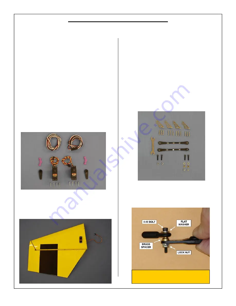
2. Install servo in servo well with the output shaft
toward the leading edge of the stab. Fish the
servo lead through the stab and out of the stab
root rib as shown.
2. Correct installation of ball link, flat washer and
brass spacer to servo arm shown below.
1. Gather the following items for installing the ele-
vator linkage:
◊
2 - 4-40 3” pushrods-With carbon reinforcement
sleeves
◊
4 - 4-40 ball link assemblies
◊
2 - Brass spacers
◊
2 - Flat washer
◊
2 - Left control horns
◊
2 - Right control horns
◊
12 - Wood screws
◊
1 - Adjustment wrench
Elevator Control Linkage Installation
Note:
Flat washer prevents ball link
from coming off brass ball.
Elevator Servo Installation
1.
The elevators have been pre-hinged and
glued
to the stabs and are ready for flight. No other
steps are necessary for hinging. Clear
covering has been provided for sealing of the
hinge gaps if desired.
Gather the following items for installing the
elevator servo:
◊
2 - Stab/elevator assembly
◊
2 - Elevator servo
◊
2 - 1 1/2” Servo Arm
◊
8 - Servo Mounting Screws (Micro Fastener
Part number
STW0209
recommended)
◊
2 - 48” servo extension
◊
2 - Aeroworks Safety Clips
Note:
48” servo extension will be used to
connect servos to receiver during a later
step.


