P a g e
|
18
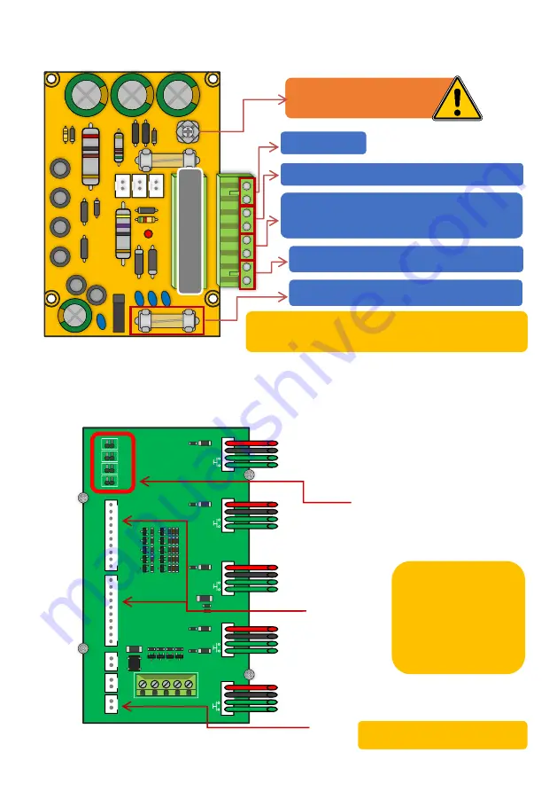
Overview of Surge PCB (
7
)
Overview of Multibutton PCB (
4
)
*Multibutton Systems Only
Earth Rod MUST be connected for
warranty.
Power Output
NOT USED
24v INPUT
–
Use provided power supply or hook up to
24v solar system.
(DO NOT USE 12v HERE)
12v DC
–
Battery backup
1 Amp Quick Blow Input Fuse (REPLACEABLE)
Must use a 30 Watt solar panel (minimum) and at least 2 x 10Ah
batteries to supply a regulated 24v
1
2
V
|
2
4
IN
|
SO
L
|
O
UT
GN
D
24V
GN
D
24
V
GN
D
24V
GN
D
24V
GN
D
24V
1
2
3
4
5
DC
24V
(IN
)
DC
24V
(O
UT)
DC
24V
(O
UT)
1
2
3
4
5
6
7
8
9
GN
D
1
2
3
4
5
6
7
8
9
GN
D
J1
J2
J3
J4
G
N
D
Note:
Connections will be pre-wired.
PANEL BUTTON
CONFIGURATION
No Jumper = 1-5
J1 = 6-10
J2 = 11-15
J3 = 16-20
J4 = 21-25
Button illumination PCB
(Button numbers are determined
by the position of the jumper link
and button plug. A paper insert will
show the button number position
for convenience.)
10-Way
Connection
Cable
24V DC
IN & OUT
Summary of Contents for MultiCOM Cellular Series
Page 3: ...P a g e 3 PHASE 1 Site Survey...
Page 5: ...P a g e 5 PHASE 2 Product Overview...
Page 6: ...P a g e 6 Overview of Intercoms Imperial Design Antenna Separate...
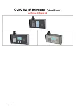
Page 7: ...P a g e 7 Overview of Intercoms Pedestal Design Antenna Integrated...
Page 8: ...P a g e 8 Overview of Intercoms Flush Design Antenna Separate...
Page 9: ...P a g e 9 Overview of Intercoms Modular Pre Set Design Antenna Separate...
Page 22: ...P a g e 22 PHASE 3a Setup Programming To be done before installing the intercom...
Page 29: ...P a g e 29 PHASE 3b PC Programming Windows Compatible Only...
Page 40: ...P a g e 40 PHASE 5 Installation...
Page 46: ...P a g e 46 PHASE 7 Aftercare...
Page 54: ...P a g e 54...
Page 55: ...P a g e 55...


