P a g e
|
25
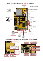
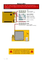
Status LEDs
CPU
Flashing = standby
Constant ON/OFF = busy
SIGNAL STRENGTH
1 flash = poor (1 bar)
2 flashes = low (2 bars)
3 flashes = good (3 bars)
4 flashes = Strong (4 bars)
5 flashes = searching
POWER
MODEM
Flashing = standby
Constant ON/OFF = searching
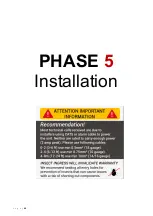
Do NOT use fine gauge cable such as CAT5, CAT6, Alarm Cable
etc to power this device as damage will occur.
0-2 metres (6 feet)
– min 0.50mm
2
(18 gauge)
2-4 metres (12 feet)
– min 0.75mm
2
(16 gauge)
4-8 metres (24 feet)
– min 1.0mm
2
(14 gauge)
The CPU, signal strength and power status LEDs are underneath the
modem and so the diagram below shows the board without the modem for
convenience.
Summary of Contents for MultiCOM Cellular Series
Page 3: ...P a g e 3 PHASE 1 Site Survey...
Page 5: ...P a g e 5 PHASE 2 Product Overview...
Page 6: ...P a g e 6 Overview of Intercoms Imperial Design Antenna Separate...
Page 7: ...P a g e 7 Overview of Intercoms Pedestal Design Antenna Integrated...
Page 8: ...P a g e 8 Overview of Intercoms Flush Design Antenna Separate...
Page 9: ...P a g e 9 Overview of Intercoms Modular Pre Set Design Antenna Separate...
Page 22: ...P a g e 22 PHASE 3a Setup Programming To be done before installing the intercom...
Page 29: ...P a g e 29 PHASE 3b PC Programming Windows Compatible Only...
Page 40: ...P a g e 40 PHASE 5 Installation...
Page 46: ...P a g e 46 PHASE 7 Aftercare...
Page 54: ...P a g e 54...
Page 55: ...P a g e 55...

