


+ User Manual
source. Choose between a cheap ATX power supply, a simple laptop 18-20 Volt adapter, an
adjustable lab bench supply, an industrial 24 Volt supply or whatever is available and can
deliver sufficient power for your application.
3D printer specific I/O view
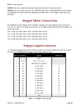
Stepper outputs
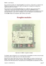
The BeBoPr has no integrated stepper drivers, but offers four sockets that accept Pololu,
StepStick or other compatible modules. If these modules are used, the motors connect to the
connectors next to the module sockets on the BeBoPr.
Applications requiring 5 axes, or more powerful stepper drivers, can connect these off-board
drivers to the connector that is located between the Pololu sockets and that carries all
relevant signals for up to 5 axes.
Limit switch inputs
These inputs accept a mix of mechanical switches and/or optical-sensors. They can connect
directly to slow changing input signals because of the Schmitt Trigger inputs. Each input has a
5 Volt supply pin for external sensors that need power to operate. This supply can deliver 0.3A
for all inputs combined and is short circuit protected by a thermal fuse.
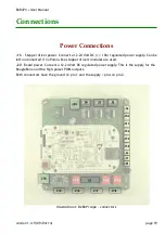
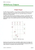
Power outputs
Three powerful outputs can generate PWM signals for motors and/or heaters, or analogue
signals for laser power control. These outputs can be controlled directly by the high
resolution PWM controllers in the AM335X processor, or via GPIO signals for bit-bang or simple
on/off control.
The output closest to the board power input connector J20 is dimensioned to deliver 120 W to
200 W, depending on the voltage used (10A @ 12 Volts or 8A @ 24 Volts). The other two
outputs can deliver 4A each (50 W @ 12 Volts or 100 W at 24 Volts).
Note that the combined
current drawn should not exceed the 16 A specification!
.
The power switching FETs have very low R
DSon
and are driven by MOSFET drivers. They can
operate at high switching frequencies with relatively low switching losses.
Connecting inductive loads can cause all kinds of trouble, ranging from HF noise up to a
damaged BeBoPr. Always use a free-wheeling diode directly over the load. This keeps the
current loop (coil!) as small as possible and reduces the area polluted by the EMI noise.
Use of high current loads may require forced air cooling of the board (FETs, diodes and fuse).
This prevents parts from overheating, melting the solder and possibly destroying the BeBoPr,
your home or even worse. Make sure to also read the chapter on “FET power dissipation”.
Always be careful, start conservative and test. Increasing power only if you feel comfortable
with the results of the previous step.
version 1.4.9 (09/04/14)
page 12


