


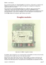

+ User Manual
WARNING: Do not exceed the maximum specified current for these connectors.
WARNING: Do not connect power to the DC INPUT (P5) jack on the BeagleBone once mounted
on the BeBoPr. This will most likely damage the BeBoPr and/or the supply connected to the
DC INPUT.
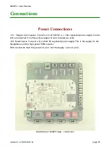
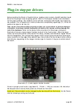
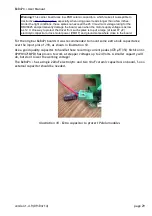
Stepper Motor Connections
If the BeBoPr has the stepper driver modules on board, the four stepper motors connect to
J15, J16, J17 and J19. In that case connector J5 is hidden underneath the driver modules and
can not be used.
J15 – X-axis, pins 1&2 motor coil-A, pins 3&4 motor coil-B
J16 – Y-axis, pins 1&2 motor coil-A, pins 3&4 motor coil-B
J17 – Z-axis, pins 1&2 motor coil-A, pins 3&4 motor coil-B
J19 – E-axis, pins 1&2 motor coil-A, pins 3&4 motor coil-B
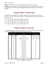
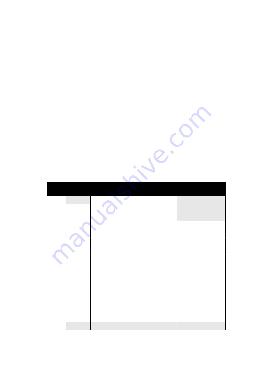
Stepper signals connector
J5 – all stepper signals are present on this connector. It connects directly to the 15 pin sub-D
connector of a TB6560-4V5 3A stepper driver board sold on e-Bay.
Pin nr Direction
Signal
AM3359 pin
1
GND
2
in/out
EXT_VCC (sense)
3
out
#STEPPER_IO_SELECT
4
out
Z_ENA_BUF
V5
5
out
Y_ENA_BUF
T4
6
out
E_DIR_BUF
U9
7
out
E_STP_BUF
R6
8
out
Z_DIR_BUF
R5
9
out
Z_STP_BUF
U5
10
out
Y_DIR_BUF
T3
11
out
Y_STP_BUF
T2
12
out
X_DIR_BUF
R4
13
out
X_STP_BUF
R3
14
out
E_ENA_BUF
V9
15
out
X_ENA_BUF
T1
16
N/C
Table 1: J5 stepper driver signals
version 1.4.9 (09/04/14)
page 20


