


+ User Manual
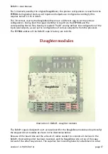
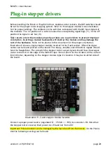
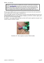
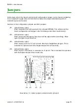
If the BeBoPr controls external stepper drivers, the stepper motors connect directly to these
drivers and the connectors J15, J16, J17 and J19 are not used. The stepper signals for the
external drivers connect to J5.
Thermistor connectors
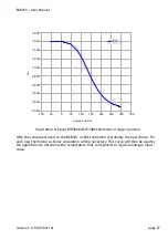
Designed for use with 100k
Ω
thermistors (e.g. Epcos B57560G104F) or any low impedance
analogue signal source. For the latter one should take into account that a 3.60 Volt voltage
source with an internal resistance of 2.05 kΩ is connected parallel to the input pins.
J6 – Thermistor 0 – BeagleBone AIN4 and ADS1015 channel 0
J7 – Thermistor 1 – BeagleBone AIN5 and ADS1015 channel 1
J8 – Thermistor 2 – BeagleBone AIN6 and ADS1015 channel 2
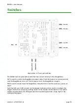
Limit switch connectors
J9
– X-max limit sensor – BeagleBone gpio69
J10 – X-min limit sensor – BeagleBone gpio67
J11 – Y-max limit sensor – BeagleBone gpio26
J12 – Y-min limit sensor – BeagleBone gpio68
J13 – Z-max limit sensor – BeagleBone gpio33
J14 – Z-min limit sensor – BeagleBone gpio27
All limit switches have a +5 Volt supply pin (pin1), a ground pin (pin 3) and a signal pin in-
between (pin 2). The input is pulled high to the 5 Volt by a 560 Ω pull-up resistor in series
with a LED. Connecting pin 2 to the ground (pin 3) will activate the LED and change the signal
on the gpio pin of the BeagleBone to a '1' (active).
Because of the hysteresis built into the input level shifters, these can connect directly to
optical slot sensors with an open collector (-like) output. In that situation the LED may
continue to glow weakly in the off situation, but that is clearly distinguishable.
Note 1: The IO enable must be active before the inputs signals can be seen by the
BeagleBone.
Note 2: The level shifter is inverting the input signal, so a 'low' input signal will activate the
LED and read back as a '1' on the BeagleBone gpio input.
PWM / analogue outputs
J2 – PWM0 – BeagleBone ehrpwm2B
J3 – PWM1 – BeagleBone ehrpwm2A
J4 – PWM2 – BeagleBone ehrpwm1A
version 1.4.9 (09/04/14)
page 21


