


+ User Manual
PWM Power Outputs
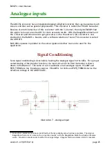
Output stages
The PWM outputs on the + can be configured in software to operate at up to very high
frequencies. 100 kHz PWM at 10 A is possible, but this will generate a lot of EMI and some
dissipation in the FETs. It's advisable to use a more conservative frequency to reduce the
amount of heat and EMI generated.
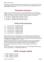
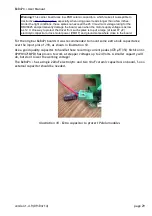
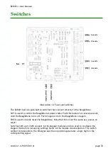
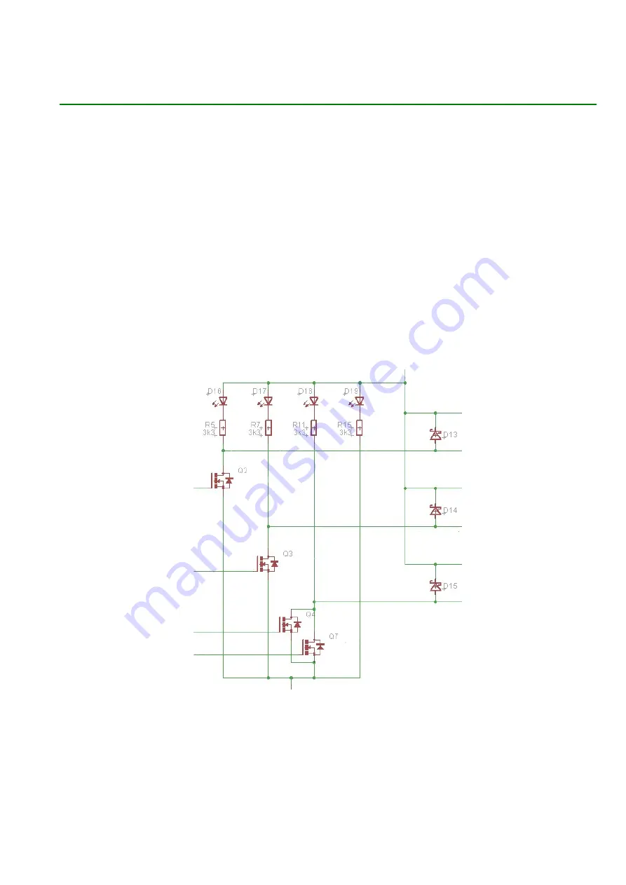
The MOSFET output stages are shown in illustration 5. The fused 12 - 24 Volt power comes in
at the top connection. On the right side the wires go to the three output connectors. The
wires on the left side connect to the push-pull MOSFET drivers used to drive the gates. The
third (bottom) output is the 10A HBP/bed output and it has two FETs in parallel to reduce the
dissipation.
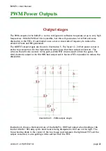
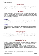
Illustration 6 shows a thermal picture of the + HBP/bed output when feeding a 10A
load at 40 kHz / 98% duty-cycle. Most heat is being dissipated in the fuse on the right. The
free-wheeling diode in the center of the top image (just between the rightmost FET and the
output connector) is also getting a little warmer than the FETs.
version 1.4.9 (09/04/14)
page 22
Illustration 5 - PWM output stages


