


+ User Manual
Power LEDs
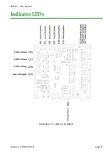
Both power LEDs (see illustration 11) are green LEDs.
The first, LED D19 in will light if the BeBoPr receives power via the board's power connector.
The LED will not light if the fuse (F1 in illustration 12) is blown.
Power LED D20 in Illustration 11) indicates that the BeagleBone is turned on.
Status LEDs
Status LEDs are either red or yellow LEDs.
A yellow LED (D21 “status” in illustration 11) is available for general use. It is connected to
gpio32
. The default configuration will make this LED blink with the BeagleBone's heartbeat
signal.
A red LED (D24 “E-stop” in illustration 11) turns on when the the emergency stop has been
activated.
The red LED (D23 “IOenable” in illustration 11) is on when the BeBoPr's input and output
signals are enabled (active).
Input signal LEDs
A yellow LEDs next to each limit switch connector indicates the state of the input. If there is
a low impedance connection between the input (pin 2) and ground (pin 3) the LED turns on.
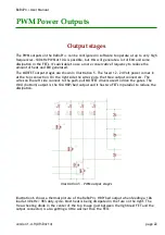
Output signal LEDs
Each PWM power output has a red LED next to the connector. The LED turns on when the
output is active.
version 1.4.9 (09/04/14)
page 32


