


+ User Manual
Improved PWM outputs
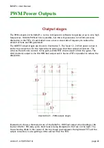
The PWM output stages have been redesigned to generate less heat in the output switches
(FETs) and allow up to 32 kHz PWM switching frequency without significant losses. The TO220
FETs have been replaced by SMD parts with lower R
DSon
. The 'heated-bed' output now can
deliver 120 Watt (10 A) at 12 Volt, or up to 200 Watt (8 A) at 24 Volt. Most heated build
platform can now connect without the need for an external mechanical or solid state relay.
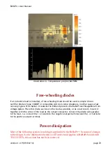
All PWM outputs now have on-board free-wheeling diodes as described in the section named
“PWM / analogue outputs“. These diodes protect the FETs (and the rest of the board) from
the voltage spikes that occur when switching at high speed or with inductive loads
I/O enable LED
This LED indicates that the I/O devices are 'live'. An inadvertently de-activated I/O enable
will prevent the I/O signals to function properly. This was not always obvious and hard to
debug, now this signal's state is directly visible.
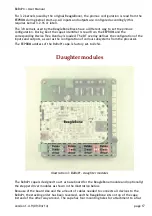
Larger bypass capacitor for stepper modules
The bulk capacitance that bypasses the stepper motors power supply has been increased. A
high quality 220 uF/50V electrolytic capacitor has been added. This should prevent damage
to the Pololu stepper driver modules caused from over-voltage spikes generated by the
motors.
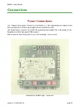
Reset button
The location of the reset button was moved to the opposite side of the board. It's now
situated next to the power button, beneath the power jack on the BeagleBone.
Sensor power
The 5 Volts on the limit sensor input connectors is no longer controlled by the BeagleBone but
available as soon as board input power is present. This supply can be used for many limit
switches that need a supply to function (e.g. optical sensors or three wire industrial proximity
sensors) or special functions that need 5 Volt when the BeagleBone is not present or has been
powered down.
† For EMC reasons it may still be necessary to mount an anti-parallel free-wheeling diode directly on the load.
version 1.4.9 (09/04/14)
page 9


