background image

4.Use and Operation Instruction

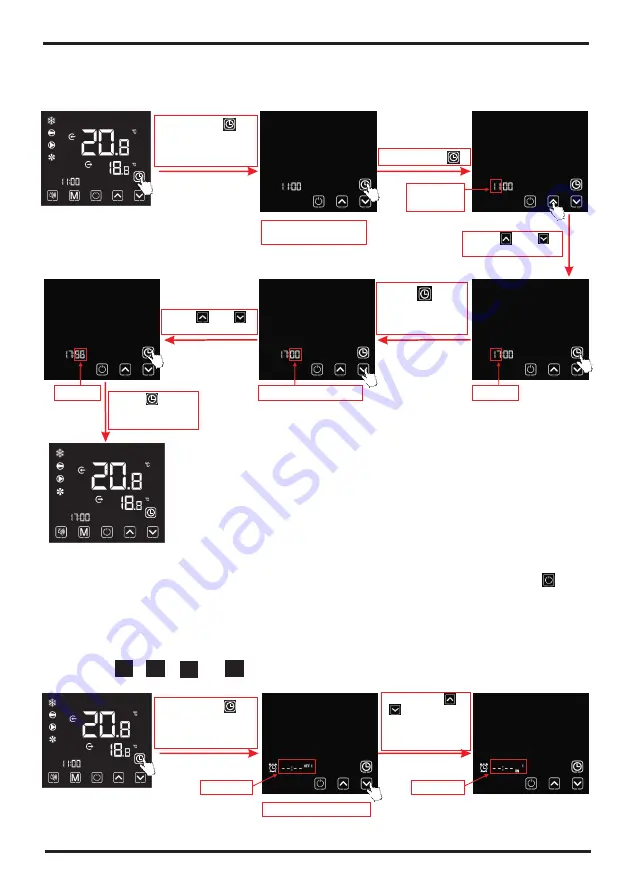
6.2 Setting and cancelling the Timer ON/OFF function

4.6. Clock setting 

6.1 System time setting 

Press "      "  to
save, and return to
the main interface


Hour digit 
flashing

System time setting 
interface 

Notes: 

, if there is no operation for 20 s, the system will 

automatically memorize use

'

s settings, and return to the main interface; if short press "      " 

during any operating steps, the changes will not be saved and return to the main interface.

Under the clock setting interface

Long press "       " 
for 2 s to enter into 
the system times 
setting interface

Short press "       "

Press "     " or 
 to adjust hour digit

"     "

Flashing

Stort press "       " 
to enter into 
the timer setting 
interface

Short press"    " or
 "    " to circularly 
display among 
timer ON1, OFF1,
 ON2 and OFF2


6.2.2 Select 


,  

 or 

 timer setting interface:


1

On


" "

" "  

"

"

OFF1

OFF

On2

2

Timer setting interface

Flashing

Press  "      " to 
save the settings 
and skip to the 
minute digit setting 

Minute digit flashing

Flashing

Flashing

Press "     " or 
to adjust minute digit

"     "

6.2.1 The wire controller can set up a two-stage timing switch: Timer ON1~ OFF1;Timer ON2~OFF2.

18

4.Use and Operation Instruction

Notes: Under the temperature setting interface, if short press "        ", the system will return to 
the main interface without any changes saved; If there is no operation for 5 s or short press
"        ", the current mode will be saved, and return to the main interface.

Short press"        " for to switch the 
mode circularly, after no operation
 for 2s, the current mode will be saved.  

Cooling mode 

Automatic mode 

2). When the unit is under the defrosting state, the defrosting symbol is on,with the display 
interface as follows:

Notes: 
1).After completing the defrosting, the unit will be automatically switched to the heating/
automatic  mode (keeping consistent with the mode before defrosting). 
During the defrosting, mode switch is available. And when switching the mode, the unit won

'

work under a new mode until defrosting is completed.

Heating mode 

Operation descriptions: 
1). Mode switch operation can only be conducted in the main interface.  

4.5. Temperature setting

Press "      " or "       " for increasing
 or decreasing target temperature.  

Defrosting state

17

Summary of Contents for hydro-pro PX

Page 1: ...INVERTER TYPE PX SWIMMING POOL HEAT PUMP UNIT Installation Instruction Manual SALES SERVICE 01842 819130 ...

Page 2: ...switch 4 5 4 6 4 7 Silent 4 8 4 9 4 10 4 11 4 12 Main board 5 Maintenance and Inspection 6 Appendix Installation illustration Swimming Pool Heat Pumps Location Parameter list and breakdown table Interface drawin Cable specification 6 2 Comparison table of refrigerant saturation temperature Use and Operation Instruction Interface display Key and icon function instruction Startup shutdown Temperatur...

Page 3: ... type unit The indoor unit can be Discretely hidden or semi hidden to suit a luxury house Our heat pump has following characteristics 1 Durable The heat exchanger is made of PVC Titanium tube which can withstand prolonged exposure to swimming pool water 2 Installation flexibility The unit can be installed outdoors 3 Quiet operation The unit comprises an efficient rotary scroll compressor and a low...

Page 4: ... The appliance shall be stored in a room without continuously operating ignition sources for example open flames an operating gas appliance or an operating electric heater Do not pierce or burn Appliance shall be installed operated and stored in a room with a floor area larger than 30 m2 Be aware that refrigerants may not contain an odour The installation of pipe work shall be kept to a minimum 30...

Page 5: ...separately from domestic waste must be taken to a recycling centre for electric and electronic devices or handed back to the dealer when purchasing an equivalent appliance 6 Directive 2002 95 EC RoHs This product is compliant with directive 2002 95 EC RoHs concerning restrictions for the use of harmful substances in electric and electronic devices 7 The unit CANNOT be installed near the flammable ...

Page 6: ... Mitsubishi R32 1 Horizontal 400 800 40 42 53 22 32 50 4 9 0 5 0 32 include 1000 418 605 H provided it is correctly insulated calculation model min vol 4x heating capacity A15 W25 max vol 7x heating capacity A15 W25 MODEL kW kW kW 2 m A A V Ph Hz RPM W dB A dB A mm 3 m h kg Ton mm Hydro Pro Inverter Part nr Heating capacity A27 W27 max min Heating capacity A15 W25 max min Power input max min Swimm...

Page 7: ... 25 13 22 6 21 7 21 4 62 220 240 1 50 Mitsubishi R32 1 Horizontal 400 750 75 42 55 24 33 50 6 0 0 7 0 45 include 1160 470 862 MODEL kW kW kW 2 m A A V Ph Hz RPM W dB A dB A mm 3 m h kg Ton mm Hydro Pro Inverter Part nr Heating capacity A27 W27 max min Heating capacity A15 W25 max min Power input max min Swimming pool volume Rated current Minimum fuse C O P at A27 W27 C O P at A15 W25 Power supply ...

Page 8: ...3 m h kg Ton mm Hydro Pro Inverter Part nr Heating capacity A27 W27 max min Heating capacity A15 W25 max min Power input max min Swimming pool volume Rated current Minimum fuse C O P at A27 W27 C O P at A15 W25 Power supply Heat exchanger Compressor brand Refrigerant Fan quantety Fan direction Fan speed Power input of Fan Noise level 1m Noise level 10m Water connection Nominal flow rate R32 Volume...

Page 9: ...3 m h kg Ton mm Hydro Pro Inverter Part nr Heating capacity A27 W27 max min Heating capacity A15 W25 max min Power input max min Swimming pool volume Rated current Minimum fuse C O P at A27 W27 C O P at A15 W25 Power supply Heat exchanger Compressor brand Refrigerant Fan quantety Fan direction Fan speed Power input of Fan Noise level 1m Noise level 10m Water connection Nominal flow rate R32 Volume...

Page 10: ... Swimming Pool Heat Pump Unit 2 SPECIFICATION 8 Model PX7 32 PX11 32 PX14 32 unit mm Model PX17 32 unit mm 1000 418 605 350 97 5 535 767 350 101 1046 615 Water outlet Φ50 Water inlet Φ50 Water outlet Φ50 Water inlet Φ50 453 ...

Page 11: ...ing Pool Heat Pump Unit 2 SPECIFICATION 9 Model PX21 32 unit mm 862 466 96 1160 790 Water outlet Φ50 Water inlet Φ50 470 Models PX25 32 PX25T 32 PX30 32 PX30T 32 unit mm Water outlet Φ50 Water inlet Φ50 1161 775 1275 490 550 97 2 ...

Page 12: ...ntion Please follow these steps when using for the first time 1 Open valve and charge water 2 Make sure that the pump and the water in pipe have been filled with water 3 Close the valve and start the unit ATTN It is necessary that the water in pipe is higher than the pool surface The schematic diagram is for reference only Please check the water inlet outlet label on the heat pump while plumbing i...

Page 13: ...ous source of fresh air which reduces it efficiency and may prevent adequate heat delivery 3 2 Swimming Pool Heat Pumps Location Normally the pool heat pump is installed within 7 5 metres of the pool The longer the distance from the pool the greater the heat loss from the piping For the most part the piping is buried Therefore the heat loss is minimal for runs of up to15 meters 15 meters to and fr...

Page 14: ...to the basepan and drain out through the barbed plastic condensation drain fitting on the side of the basepan This fitting is designed to accept 20mm clear vinyl tubing which can be pushed on by hand and run to a suitable drain It is easy to mistake the condensation for a water leak inside the unit NB A quick way to verify that the water is condensation is to shut off the unit and keep the pool pu...

Page 15: ...your pool pump is running when the pool temperature drops more than 0 2 below set temperature Time Delay The unit is equipped with a 3 minute built in solid state restart delay included to protect control circuit components and to eliminate restart cycling and contactor chatter This time delay will automatically restart the unit approximately 3 minutes after each control circuit interruption Even ...

Page 16: ...sed to enter and exit the mute mode with one click 4 2 Key and icon function instruction Key symbols It is used to switch the unit mode temperature setting and parameter setting It is used to carry out startup shutdown cancel current operation and return to the last level of operation It is used to page up and increase variable value It is used to page down and decrease variable value It is used a...

Page 17: ...he unit It will display when compressor is started It will display when water pump is started It will display when fan is started When the timing mute function is started it keeps bright for a long time When it is in mute state it will flash Or else it is off It will display after the user sets the timing and multiple timing intervals can be set When the axillary display area displays the water ou...

Page 18: ...ut down the wire controller will display as follows Operations are the same as under ON OFF main interface 4 4 Mode switch Under the main interface Short press to switch the unit among heating cooling and automatic mode When there is no operation within 1 minute it will display with half screen off Notes Startup shutdown operation can only be conducted in the main interface When it displays with h...

Page 19: ...n the unit is under the defrosting state the defrosting symbol is on with the display interface as follows Notes 1 After completing the defrosting the unit will be automatically switched to the heating automatic mode keeping consistent with the mode before defrosting During the defrosting mode switch is available And when switching the mode the unit won t work under a new mode until defrosting is ...

Page 20: ...eturn to the main interface Under the clock setting interface Long press for 2 s to enter into the system times setting interface Short press Press or to adjust hour digit Flashing Stort press to enter into the timer setting interface Short press or to circularly display among timer ON1 OFF1 ON2 and OFF2 6 2 2 Select or timer setting interface 1 On OFF1 OFF On2 2 Timer setting interface Flashing P...

Page 21: ...return to the main interface While enter into the set the Timer ON OFF as below or timer setting interface 1 OFF1 OFF ON ON2 2 Take for example ON1 1 Select cancel the Timer ON OFF as below or timer setting interface refers to 6 2 1 1 OFF1 OFF ON ON2 2 Take for example ON1 Note Under the Timer ON OFF setting interface if the timing symbol and entire time digits flash at the same time click to retu...

Page 22: ...long press of for 2 s Short press or Short press for entering the hour digit setting of timing on silent Short press or Short press for confirming the timing on silent and turn to the setting of timing off silent Short press for entering the hour digit setting of timing off silent Short press or Short press for confirming timing off silent saving the changes and returning to the main interface Sho...

Page 23: ... the screen will be lighten after other operations conducted 2 Under the OFF interface locking operation is available and the operation method is the same as locking screen under the ON interface 2 Two or more faults 1 Single fault Short press or Fault code Fault serial number Quantity of fault Short press For example Notes 1 When the silent icon is lighten The timing mute has been set but it s no...

Page 24: ...r Check the pressure switch and cold circuit Check or change the temp Sensor Check the pressure switch and cold circuit check and replace this temp sensor Check whether fan motor is broken or locked or not Inlet Temp Sensor Fault PP Pressure sensor Fault The temp Sensor is broken or short circuit The temp Sensor is broken or short circuit The temp Sensor is broken or short circuit The temp Sensor ...

Page 25: ...version board hardware Check whether current return wires connected motor Check and adjust the current measurement Check the input voltage measurement Check the input voltage measurement Check the input voltage measurement Check the input voltage measurement Check and adjust the current measurement Check the communication connection Check the PFC switch tube short circuit or not Check and adjust t...

Page 26: ...V25T 32 PIV30 32 PIV30T 32 1 Wire control interface diagram and definition 4 11 Interface drawin AC L OUT1 OUT2 CN2 CN8 CN13 OUT3 AC N OUT4 OUT5 PC1004 CN9 GND GND GND GND GND GND GND GND GND GND GND GND AI DI12 AI DI11 AI DI10 AI DI09 AI DI08 AI DI07 AI DI06 AI DI05 AI DI04 AI DI03 AI DI02 AI DI01 12V 0 10V_OUT PWM_OUT PWM_IN GND GND GND GND 5V AI DI13 GND GND RS485_B_2 RS485_A_2 12V GND RS485_B_...

Page 27: ... 220 230VAC Live wire input 220 230VAC Neutral wire input 220 230VAC Emergency switch input Water flow switch input System low pressure input System high pressure input Water output temperature input System fan coil temperature input Ambient temperature input Mode switch input Master slave machine switch Antifreeze temperature input System Exhaust temperature input Compressor current detection Pre...

Page 28: ...ller interface diagram and definition 4 12 Main board PIV7 32 PIV11 32 PIV14 32 4 Use and Operation Instruction 1 2 3 1 2 1 2 A B 1 2 1 2 4 5 6 3 1 2 4 5 6 3 1 2 1 2 1 2 4 5 6 3 7 8 9 1 2 ACN1 ACL1 P03 GND 26 ...

Page 29: ...1 2 3 1 2 1 2 A B 1 2 1 2 4 5 6 3 1 2 4 5 6 3 1 2 1 2 1 2 4 5 6 3 7 8 9 Controller interface diagram and definition 4 11 Main board PIV17 32 PIV21 32 4 Use and Operation Instruction 1 2 P03 GND 27 ...

Page 30: ...t Water output temperature input System fan coil temperature input Ambient temperature input System Exhaust temperature input Earth wire Earth wire System suction temperature input Water input temperature input P10 U P10 V P10 W CN18 EMV CN13 HEAT CN96 H CN96 L P1 AC L P2 AC N CN99 PL CN29 OVT CN30 HP CN31 LP CN7 OAT CN21 RES1 CN22 RES2 CN8 OPT CN12 PH CN9 OHT P00 GND P01 GND P13 L P14 L R485 B R4...

Page 31: ...n systems containing flammable refrigerants safety checks are necessary to ensure that the risk of ignition is minimised For repair to the refrigerating system the following precautions shall be complied with prior to conducting work on the system Work procedure Work shall be undertaken under a controlled procedure so as to minimise the risk of a flammable gas or vapour being present while the wor...

Page 32: ...ll be applied to installations using flammable refrigerants The charge size is in accordance with the room size within which the refrigerant containing parts are installed The ventilation machinery and outlets are operating adequately and are not obstructed If an indirect refrigerating circuit is being used the secondary circuit shall be checked for the presence of refrigerant Marking to the equip...

Page 33: ...sible voltage and current permitted for the equipment in use Intrinsically safe components are the only types that can be worked on while live in the presence of a flammable atmosphere The test apparatus shall be at the correct rating Replace components only with parts specified by the manufacturer Other parts may result in the ignition of refrigerant in the atmosphere from a leak Cabling Check th...

Page 34: ...that all refrigerants are removed safely When transferring refrigerant into cylinders ensure that only appropriate refrigerant recovery cylinders are employed Ensure that the correct number of cylinders for holding the total system charge is available All cylinders to be used are designated for the recovered refrigerant and labelled for that refrigerant i e special cylinders for the recovery of re...

Page 35: ...efrigerant It is essential that electrical power is available before the task is commenced a Become familiar with the equipment and its operation b Isolate system electrically c Before attempting the procedure ensure that Mechanical handling equipment is available if required for handling refrigerant cylinders All personal protective equipment is available and being used correctly The recovery pro...

Page 36: ...ine MCB Creepage protector Signal line 2 n 0 5mm Nameplate maximum current Earth line No more than 10A 20A 32A 40A 40A 63A 80A 100A 125A 160A 225A 250A 280A 2 1 5mm 2 2 5mm 2 4mm 2 6mm 2 10mm 2 16mm 2 mm 25 2 mm 25 2 35mm 2 50mm 2 70mm 2 95mm 2 Three phase unit 2 3 1 5mm 2 3 2 5mm 2 3 4mm 2 3 6mm 2 3 10mm 2 16mm 3 2 25mm 3 2 3 25mm 2 3 35mm 2 3 50mm 2 3 70mm 2 3 95mm 30mA less than 0 1 sec 30mA le...

Page 37: ...perature R410A Pressure MPa Temperature R32 Temperature R410A Temperature R32 0 0 3 0 5 0 8 1 1 3 1 5 1 8 2 2 3 2 5 2 8 3 3 3 3 5 3 8 4 4 5 5 5 5 51 3 20 9 4 11 19 24 31 35 39 52 5 20 9 3 5 10 18 23 29 5 33 3 38 7 43 47 51 55 57 61 64 70 74 80 42 46 5 49 5 53 5 56 60 62 67 5 72 5 77 4 35 ...

Page 38: ...Code ...

Reviews: