background image

PROTEAM 

G-

Silent Inverter

User Manual

Automated Environmental Systems Ltd.

Unit 1, 1 Wimbledon Avenue, Brandon, Suffolk, IP27 0NZ

01842 819130 | sales@automatedenvironmentalsystems.co.uk

Summary of Contents for PROTEAM G-Silent G108

Page 1: ...PROTEAM G Silent Inverter User Manual Automated Environmental Systems Ltd Unit 1 1 Wimbledon Avenue Brandon Suffolk IP27 0NZ 01842 819130 sales automatedenvironmentalsystems co uk ...

Page 2: ...D Installation guidance 8 1 Installation reminder 8 2 Wiring 9 3 Electrical wiring diagram 10 4 References for protecting devices and cable specification 10 E Instructions for Operation 11 1 Key Function 11 2 Operation Instruction 12 F Testing 14 1 Inspect heat pump before use 14 2 Leakage detection notice and method 14 3 Trial 15 G Maintenance 16 H Trouble shooting for common faults 17 I Water pu...

Page 3: ... Pump 1 A Foreword Thank you for choosing our inverter pool heat pump which is designed to be more silent and more energy efficient than all previous models We hope you ll be able to enjoy your pool for longer now Thank you ...

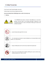
Page 4: ... heat pump The WARNING sign denotes a hazard It calls attention to a procedure practice or the like which if not correctly performed or adhered to could result in personal injury or injury to a third party These signs are rare but are extremely important Keep the heat pump away from fire source The heat pump must be placed in well ventilated area it is not permitted to install it indoors or in a c...

Page 5: ...educe heat loss It is also recommended that a suitable pool cover be installed on the pool at all times when the pool is not in use i For maximum efficiency the connecting pipes between the pool filter and the heat pump should be insulated and as short as practically possible if over 10m extra thick insulation on the waterpipe is recommended j Do not accelerate the defrosting process by any means ...

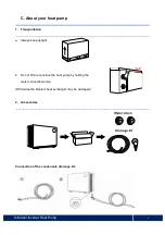
Page 6: ...ur heat pump 1 Transportation a Always keep upright b Do not lift at or position the heat pump by holding the water connection union Otherwise the titanium heat exchanger may be damaged 2 Accessories Connection of the condensate drainage kit ...

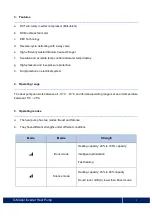
Page 7: ...ressure protection h Full protection on electrical system 4 Operating range The heat pump can work between air 10 C 43 C and its ideal operating range is at an air temperature between 15 C 25 C 5 Operating modes a The heat pump has two modes Boost and Silence b They have different strengths under different conditions Mode Modes Strength Boost mode Heating capacity 20 to 100 capacity Intelligent op...

Page 8: ... 8 7 1 16 0 7 2 15 8 7 1 15 5 7 PERFORMANCE CONDITION Air 15 C Water 26 C Humid 70 Heating capacity kW 5 0 6 6 7 7 9 0 10 5 12 5 14 5 19 0 19 0 24 2 COP Range 7 3 4 5 7 5 4 8 7 3 4 7 7 5 5 0 7 7 4 9 7 7 5 0 7 1 5 0 8 0 5 0 8 0 5 0 7 5 5 TECHNICAL SPECIFICATION Advised pool surface m2 With Cover 15 40 20 60 30 75 35 90 40 100 40 110 50 125 60 160 60 175 85 200 Operating air temperature C 10 C 43 C ...

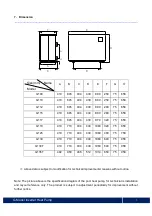
Page 9: ...duct is subject to adjustment periodically for improvement without further notice A B C D E F G H G108 410 645 404 430 890 250 75 658 G110 410 645 404 430 890 250 75 658 G112 410 645 404 430 890 290 75 658 G115 410 645 404 430 890 280 75 658 G117 410 645 404 430 970 320 75 658 G119 410 710 404 430 1060 320 75 658 G125 410 710 404 430 1060 460 75 758 G130 410 710 404 430 1060 640 75 958 G130T 410 7...

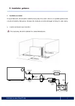
Page 10: ...nals are allowed to install the heat pump End users who are not qualified professionals should not install by themselves otherwise the heat pump could be damaged and risky for users safety a Location and water pipe connection The heat pump should be installed in a well ventilated place 1000mm ...

Page 11: ...r for the recommended water flow of the circulation pump please refer to the Technical Specifications of the heat pump 4 When the machine is running there will be condensation water from the bottom Please place the drainage nozzle accessory into the hole and connect a hose to drain the condensation water away b The inlet and outlet water unions can t stand the weight of soft pipes The heat pump mu...

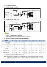
Page 12: ...m 2 must be increased The signal cable can be extended to 50m maximum MODEL G108 G110 G112 G115 G117 G119 G125 G130 G130T G135T Breaker Rated Current A 9 10 5 12 14 5 16 5 18 21 24 9 12 Rated Residual Action Current mA 30 30 30 30 30 30 30 30 30 30 Fuse A 9 10 5 12 14 5 16 5 18 21 24 9 12 Power Cord mm 2 3x1 5 3 x 2 5 3 x 2 5 3 x 2 5 3 x 2 5 3 x 4 3 x 4 3 x 6 5 x 2 5 5 x 2 5 Signal cable mm 2 3 0 ...

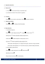
Page 13: ...Heating cooling models 1 Power On Off 2 Wi Fi setting 1 Lock Unlock Screen 2 Heating mode 18 40 C 3 Cooling mode 12 30 C 4 Auto mode 12 40 C 1 Boost 2 Silence Temperature Setting Attention i The controller has power down memory function ii The buttons will turn dark when it s locked ...

Page 14: ...ooling Auto Press to switch between heating cooling and auto mode Heating mode Water temperature setting range 18 40 C Cooling mode Water temperature setting range 12 30 C Auto mode Water temperature setting range 12 40 C When water inlet temperature is 1 C higher than set point automatic cooling mode starts When water inlet temperature is 1 C lower than set point automatic heating mode starts 2 S...

Page 15: ...to Wi Fi the icon remains on f Defrosting 1 Automatic defrosting when machine is auto defrosting will flash and return to previous working mode when it finishes 2 Manual Defrosting To enter forced defrosting mode the compressor must be working for more than 10 minutes in heating mode press and on touch controller simultaneously for 5 seconds to start forced defrosting when flashes the defrost cycl...

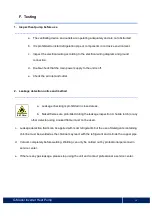
Page 16: ...t 2 Leakage detection notice and method a Leakage checking is prohibited in closed areas b Naked flames are prohibited during the leakage inspection A halide torch or any other detector using a naked flame must not be used c Leakage detection fluids can be applied with most refrigerants but the use of detergents containing chlorine must be avoided as the chlorine may react with the refrigerant and...

Page 17: ...re starting the heat pump please check for any water leakage c In order to protect itself the heat pump is equipped with a time lag starting function the fan will start working 1 minute before the compressor when starting the machine and it will stop running 1 minute after the compressor when the machine is switched off d After starting up heat pump start up please check for any strange noise from...

Page 18: ...connections regularly 4 If repair or disposal of the unit is required please contact the nearest authorized service center 5 Do not attempt to work on the equipment by yourself Improper operation can be dangerous 6 A safety inspection must be carried before any maintenance or repair work is carried out on heat pumps with R32 gas Important Unscrew and disconnect the water nozzle of inlet pipe to le...

Page 19: ...hority which authorizes them to handle refrigerants safely in accordance with industry recognized standards and regulations d Do not attempt to work on the equipment by yourself Improper operation can be dangerous e Strictly comply with the manufacturer s requirements when charging R32 gas and carrying out equipment maintenance This chapter focuses on special maintenance requirements for swimming ...

Page 20: ... Air outlet blocked Remove obstructions 3 minutes start delay Wait patiently Display normal but no heating Set temp too low Set proper heating temp 3 minutes start delay Wait patiently If above solutions don t work please contact your installer with detailed information and your model number Don t try to repair it yourself Note If the following conditions happen please stop the machine immediately...

Page 21: ...nly in cooling mode 7 P0 Controller communication failure 8 P1 Water inlet temp sensor failure 9 P2 Water outlet temp sensor failure 10 P3 Gas exhaust temp sensor failure 11 P4 Evaporator coil pipe temp sensor failure 12 P5 Gas return temp sensor failure 13 P6 Cooling coil pipe temp sensor failure 14 P7 Ambient temp sensor failure 15 P8 Cooling plate sensor failure 16 P9 Current sensor failure 17 ...

Page 22: ...Power Supply 230V 50Hz Customer prepare Power Supply 230V 50Hz Earthing control connection Power cable Customer remote control switch connector Water pump 230V voltage 500W capacity Breaker fuse Customer prepare Water Breaker fuse Customer prepare Contactor 20 Customer remote control switch connector Water Pump ...

Page 23: ...tomer prepare Earthing Power Supply 230V 50Hz Customer prepare Power Supply 230V 50Hz Earthing Power cable Water pump 230V voltage 500W capacity Breaker fuse Customer prepare Breaker fuse Customer prepare Contactor 21 Customer remote control switch connector Water Pump ...

Page 24: ...ustomer prepare Power Supply 400V 50Hz Earthing Load on connection to the heat pump over 500 Watt must have an external contactor by the heat pump Both line L N and all 3 phases must be in 400V voltage Breaker fuse Customer prepare Breaker fuse Customer prepare Contactor Power cable 22 Load on connection to the heat pump over 500 Watt must have an external contactor by the heat pump Both line L N ...

Page 25: ...nected Water pump control and timer connection 1 Water filtration pump timern 2 Water filtration pump wiring of Heat Pump Note The installer should connect 1 parallel with 2 as above picture To start the water pump condition 1 or 2 is connected To stop the water pump both 1 and 2 should be disconnected 23 Note The installer should connect 1 parallel with 2 as above picture To start the water pump ...

Page 26: ...G Model Inverter Heat Pump J Wi Fi operation Inverter Heat Pump 24 ...

Page 27: ...G Model Inverter Heat Pump 25 ...

Page 28: ...G Model Inverter Heat Pump 26 ...

Page 29: ...G Model Inverter Heat Pump 27 ...

Page 30: ...G Model Inverter Heat Pump 28 ...

Page 31: ...G Model Inverter Heat Pump 29 ...

Page 32: ...AQ05MC R32 Automated Environmental Systems Ltd Unit 1 1 Wimbledon Avenue Brandon Suffolk IP27 0NZ 01842 819130 sales automatedenvironmentalsystems co uk ...

Reviews: