G-Model Inverter Heat Pump
10
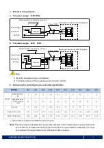
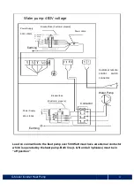
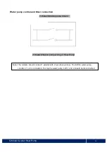
3. Electrical wiring diagram
a. For power supply: 230V 50Hz
b.
For power supply: 400V 50Hz
Note
:
1) Must be hard wired, plug is not allowed.
2) The heat pump must have a good ground connection (earth).
4. References for protecting devices and cable specification
※
Above data is subject to modification without notice.
Note:
The above data is calculated for a power cable of length ≤ 10m. Voltage drop on power cable must
be less than 10 Volt when the heat pump is at full load. For longer cables the diameter
(mm
2
)
must
be increased. The signal cable can be extended to 50m maximum.
MODEL
G108
G110
G112
G115
G117
G119
G125
G130
G130T
G135T
Breaker
Rated Current
(A)
9
10.5
12
14.5
16.5
18
21
24
9
12
Rated Residual
Action Current
(mA)
30
30
30
30
30
30
30
30
30
30
Fuse (A)
9
10.5
12
14.5
16.5
18
21
24
9
12
Power Cord (mm
2
)
3x1.5
3 x 2.5
3 x 2.5
3 x 2.5
3 x 2.5
3 x 4
3 x 4
3 x 6
5 x 2.5
5 x 2.5
Signal cable (mm
2
)
3×0.5
3×0.5
3×0.5
3×0.5
3×0.5
3×0.5
3×0.5
3×0.5
3×0.5
3 x 0.5
Distribution Box (provided by customer)
Earthing
Power Supply
230V 50Hz
Breaker
Fuse
Power Cable
Swimming Pool Heat Pump Wiring Board
Distribution Box (provided by customer)
Power Supply
400V 50Hz
Earthing
Breaker
Fuse
Power Cable
Swimming Pool Heat Pump Wiring Board
Summary of Contents for PROTEAM G-Silent G108
Page 26: ...G Model Inverter Heat Pump J Wi Fi operation Inverter Heat Pump 24 ...
Page 27: ...G Model Inverter Heat Pump 25 ...
Page 28: ...G Model Inverter Heat Pump 26 ...
Page 29: ...G Model Inverter Heat Pump 27 ...
Page 30: ...G Model Inverter Heat Pump 28 ...
Page 31: ...G Model Inverter Heat Pump 29 ...


