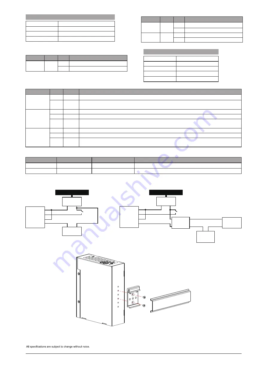
IP Address
192.168.1.1
Subnet Mask
255.255.255.0
User Name
Password
DEFAULTS
Power LEDs
LED
Color State Description
Power1
Green On
Powered on correctly.
Off
Not receiving power from power1.
Power2
Green On
Powered on correctly.
Off
Not receiving power from power1.
DO LED
LED
Color State Description
System
Yellow On
DO ON
Off
DO OFF
Baud rate
115200
Stop bits
1
Data bits
8
Parity
N
Flow control
none
Console Port Defaults
Port Status LEDs
LED
Color State
Description
RJ45 Ports
Up (PoE)
Amber On
The port is enabled and supplying power to connected device.
-
Off
The port has no active connection, or it is not connected to a PoE PD device. Otherwise, the port may
have been disabled through the switch user interface.
RJ45 Ports
Down (LAN)
Green On
The port is enabled and established a link to connected device.
-
Off
The port has no active network connection, or it has no established link to connected device.
Otherwise, the port may have been disabled through the switch user interface.
SFP Ports
Green On
The port is enabled and supplying power to connected device.
Green Blinking
Green Blinking
The port is transmitting/receiving packets.
The port is transmitting/receiving packets.
-
Off
The port has no active network connection, or it has no established link to connected device.
Otherwise, the port may have been disabled through the switch user interface.
Reset button
Task
Method
SYS LED Behavior
Port Status LED Behavior
Reset
Press 2 ~ 7 seconds Blinking Green
All LEDs Off.
Restore Defaults Press 7 ~ 12 seconds Blinking Green
All LEDS On.
DIN Rail Installation
admin
admin
DI+
DI-
DO+
DO-
12VDC
Switch
+ -
12V device
+ -
100-240VAC Input
DI/DO Connection Diagram
100-240VAC Input
DI+
DI-
DO+
DO-
Switch
AC or DC
device
12V Relay
AC or DC
- -
+ +
AC or DC
Power
12VDC
+ -
DI/DO Connection Diagram w/ AC or DC Relay
AETEK INC.
6F, No.192-1, Lien-Cheng Rd., Chung-Ho, New Taipei City, 235, Taiwan, R.O.C.
|
T
:
+886-2-82452822
|
W
:
www.aetektec.com
|
E
:
sales@aetektec.com
Copyright © 2022 AETEK INC. All rights reserved.


