Please keep this user manual for future use. It
will expire upon publication of a revised issue
however, so please check when using this manual
if you have the latest available version.
You can check with your distributor, dealer,
AF-X Systems BV or on the website:
www.af-x.com
User Manual AF-X Fireblocker Nano Series version 3.5
14
9.
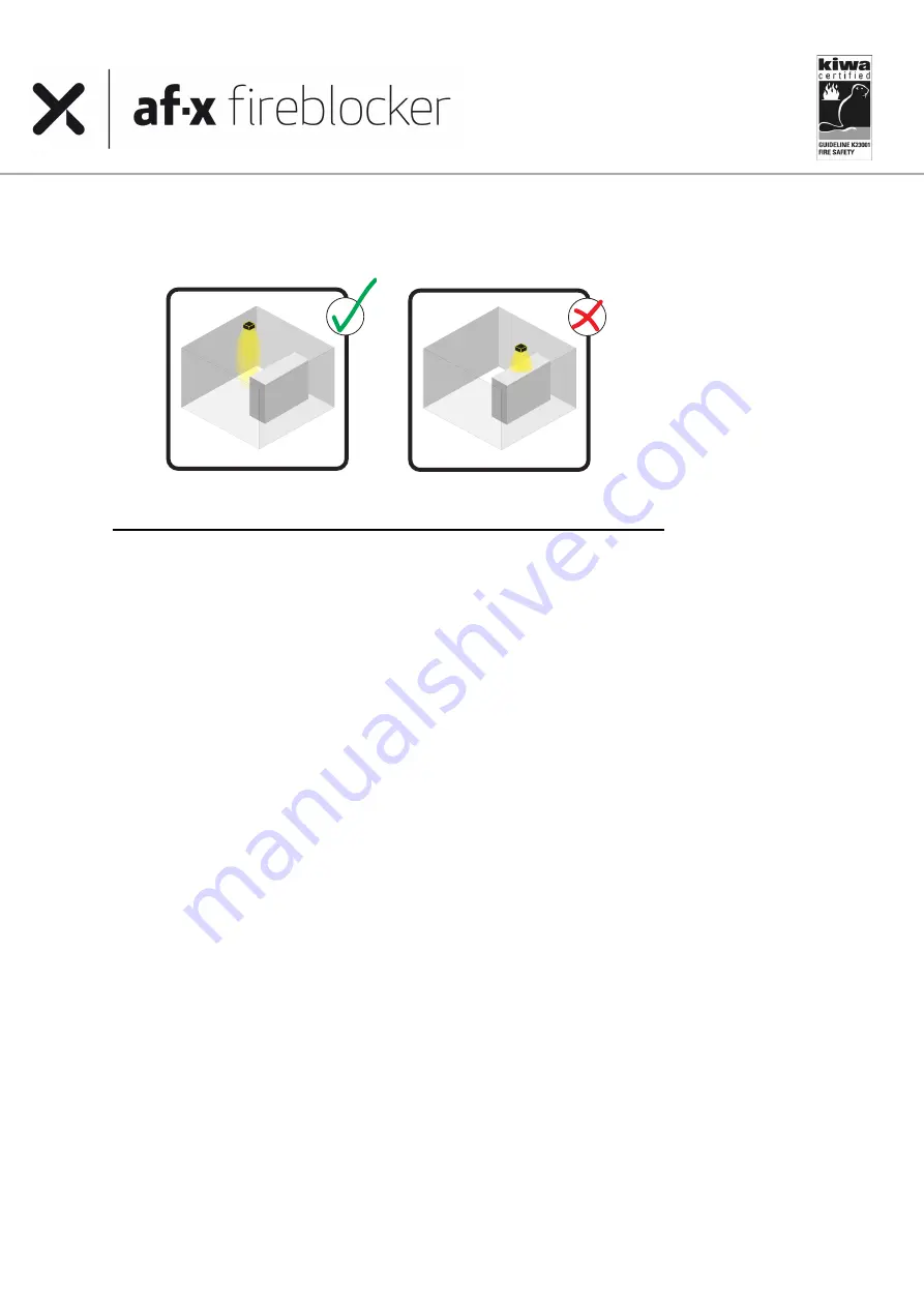
It is of the utmost importance that there are no obstacles in front of the discharge opening for a distance
as specified in 5.6
Avoid obstacles in front of discharge opening:
5.8
Mounting guidelines AF-X Fireblocker extinguishing generators
Please note that the AF-X Fireblocker Box units should be mounted under normal environmental conditions.
a)
Please study the entire system’s projection plan carefully before mounting any generators.
b)
Systems with a fire extinguishing control panel should at all times contain a system isolating switch
separating the extinguishing units from the control panel during installation as well as during
maintenance activities.
c)
For the installation of cables use the cables sold and/or advised by AF-X Systems only and make sure
that they are installed according standard or local guidelines/legislation. Always follow the cable
manufacturer’s guidelines regarding the installation of cables.
d)
Take the AF-X Fireblocker from its packaging. Check the product for visible faults or damage as a result
of transport. Some generators are packed with nozzle protection brackets and stickers. Remove them
carefully and completely to assure the free outflow of aerosol during activation.
e)
De AF-X Fireblocker generators are standard equipped with an IP55 female connector chassis (see
relevant product drawing). Using the proper tools, the installer must equip the control cable with a cable
gland, a hood and a male inlay, that AF-X Systems supplies.
f)
The AF-X Fireblocker is delivered with a short circuit safety between the poles 1 and 2 of the female inlay
in the connector. This prevents unwanted currents in the activation unit. To assure a secure and safe
installation of the generator, please keep the short circuit safety as long as possible in its safeguarding
position.
g)
The male insert is properly connected to the (massive core) control cable with a stripping length of
15mm to pole number 1 and pole number 2, using a maximum torque of 0,5 Nm. The AF-X Fireblocker is
not earthed.
h)
De AF-X Fireblocker generators must be mounted in isolation
glands and rings (even if the basic design
does not specify as such). Attach the mounting brackets, which need to comply with local rules and
regulations, to the wall, ceiling or other location, using the insulation glands and rings in all mounting
holes that connect the bracket to the mounting surface. Do this in such a way that the extinguishing
units cannot move or get damaged inadvertently.
i)
Attach the AF-X Fireblocker firmly to the mounting brackets with the clasp and ensure an unobstructed
discharge. It is very important that there be no obstacle in the space immediately in front of the
discharge for a distance of at least the length of the AF-X Fireblocker generator itself (cf. drawing above).
Always maintain distance to cable ducts. Although the AF-X aerosol’s discharge temperature should not
be damaging to the cables, it is important that the discharge cannot be influenced.


