UG 20-UG 25-OI-vers. 3.2 gb. 06.08.14.doc
11
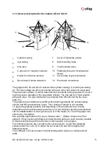
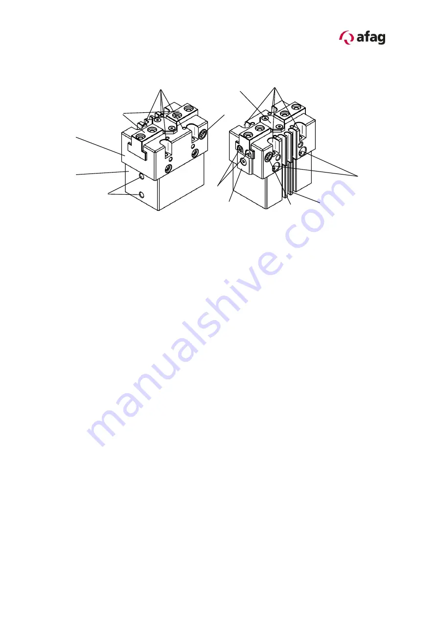
3.1.3 General description for the module UG 20 / UG 25
1
Cylinder casing
7
Cover of fastening screws
2
Jaw casing
8
Side mounting holes
3
Grip jaws
9
Top Mounting holes
4
C-grooves for magnetic sensors
10
Fastening thread of holding-down
device
5
Holder for inductive sensors
11
Cover plate of grip mechanism
6
Set screws of stroke detection
12
Pneumatic connections
The grippers UG 20 and UG 25 consist of the cylinder casing (1) and the jaw casing
(2). The two casings are firmly connected with each other and cannot be separated.
The pneumatic cylinder (1) which transmits its movements to the grip jaws (3) via two
reversing levers operates in the pneumatic cylinder. The grip jaws (3) move parallel
with each other. The grip mechanism is protected from dirt and dust by the cover
plate (11).
The grippers are available as type NN (without spring preload), NC (pressureless,
closed) and NO (pressureless, open). They change of design is not possible.
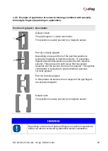
To query the gripping positions and depending on the requirement up to three
magnetic sensors (accessories) as well as up to two inductive sensors (accessories)
can be installed either in the C-grooves (4) or in the holder (5). Thus the gripper can
check up to 5 positions.
One possible application is the query „Gripper open“, „Gripper closed“ and „Part
grip
ped“. When positive grip fingers and asymmetric parts are used it is also possible
to check whether the part is held in the correct position in the gripper.
The inductive sensors are covered by the set screws (6). Loosen the fastening
screws under the cover (7) to adjust the set screws (6) and then retighten the
fastening screws.
The 4 threads (10) can be used to install holding-down devices or similar add-on
parts.
2
1
5
12
4
3
7
8
6
9
7
10
11
Summary of Contents for 50030771
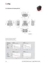
Page 14: ...14 UG 20 UG 25 OI vers 3 2 gb 06 08 14 doc 3 1 8 Dimensions drawing UG 20 ...
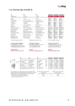
Page 15: ...UG 20 UG 25 OI vers 3 2 gb 06 08 14 doc 15 3 1 9 Technical data of the UG 20 ...
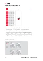
Page 16: ...16 UG 20 UG 25 OI vers 3 2 gb 06 08 14 doc 3 2 0 Preferred combinations UG 20 ...
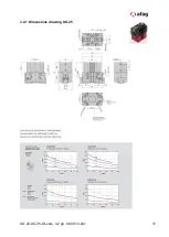
Page 17: ...UG 20 UG 25 OI vers 3 2 gb 06 08 14 doc 17 3 2 1 Dimensions drawing UG 25 ...
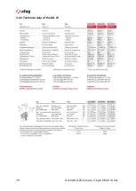
Page 18: ...18 UG 20 UG 25 OI vers 3 2 gb 06 08 14 doc 3 2 2 Technical data of the UG 25 ...
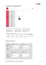
Page 19: ...UG 20 UG 25 OI vers 3 2 gb 06 08 14 doc 19 3 2 3 Preferred combinations UG 25 ...

