
20 UG 20-UG 25-OI-vers. 3.2 gb. 06.08.14.doc
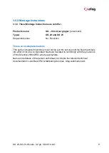
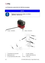
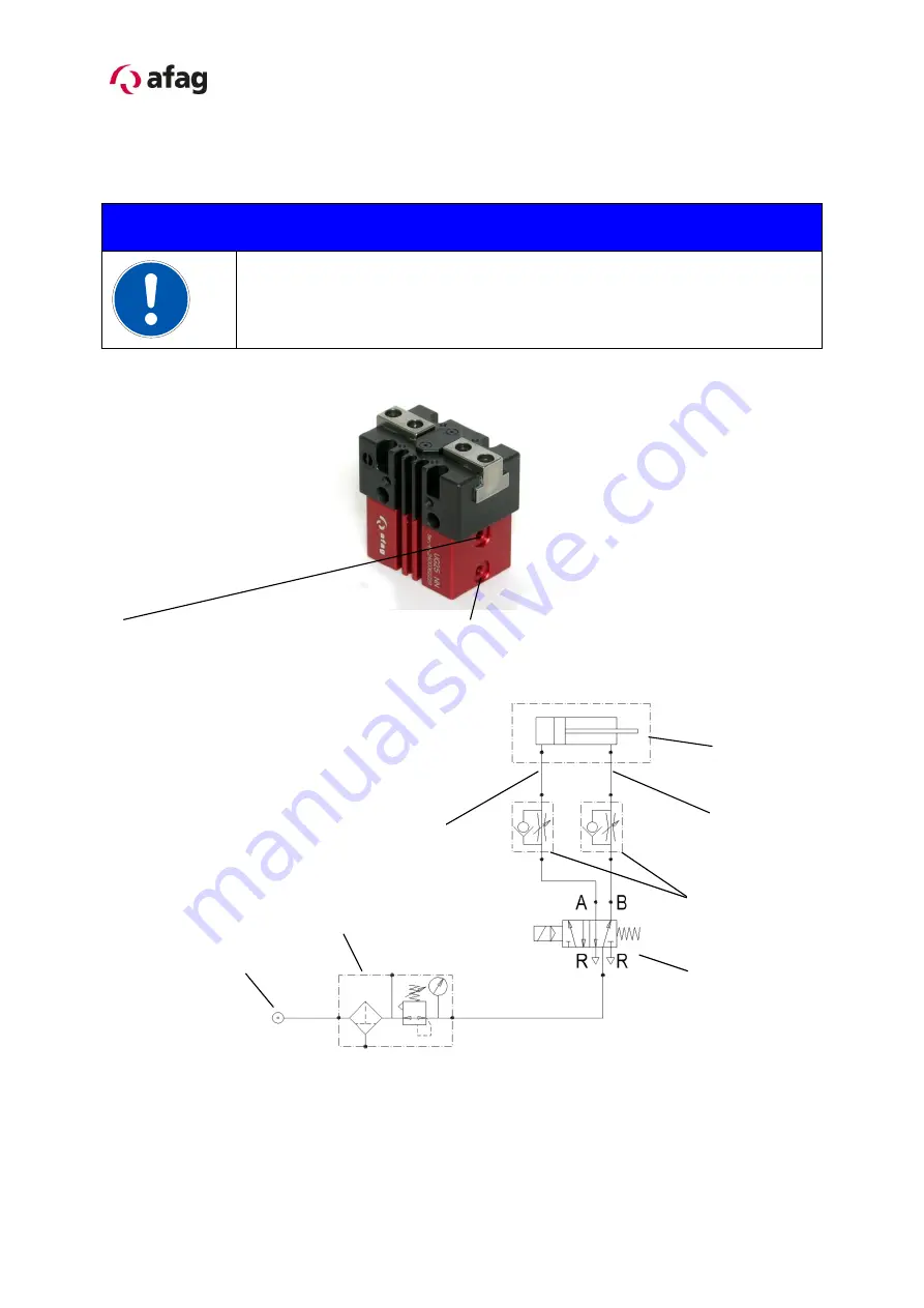
3.2.4 Pneumatic connection for the UG-Universal gripper
NOTE
Minimal compressed air quality according to
ISO 8573-1; 2010 (7-4-4)
P1
“Close” connection
P2
“Open” connection
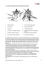
1
Compressed air connection
4
One-way restrictor
2
Maintenance unit
5
Gripper (UG 20 /UG 25)
3
5-2 port directional control valve
P1/P2
Prise d’air
1
2
4
5
3
P1
P2
Summary of Contents for 50030771
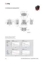
Page 14: ...14 UG 20 UG 25 OI vers 3 2 gb 06 08 14 doc 3 1 8 Dimensions drawing UG 20 ...
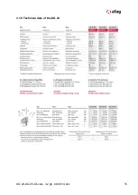
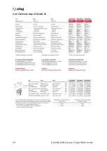
Page 15: ...UG 20 UG 25 OI vers 3 2 gb 06 08 14 doc 15 3 1 9 Technical data of the UG 20 ...
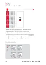
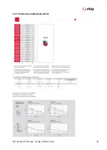
Page 16: ...16 UG 20 UG 25 OI vers 3 2 gb 06 08 14 doc 3 2 0 Preferred combinations UG 20 ...
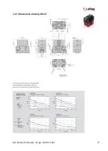
Page 17: ...UG 20 UG 25 OI vers 3 2 gb 06 08 14 doc 17 3 2 1 Dimensions drawing UG 25 ...
Page 18: ...18 UG 20 UG 25 OI vers 3 2 gb 06 08 14 doc 3 2 2 Technical data of the UG 25 ...
Page 19: ...UG 20 UG 25 OI vers 3 2 gb 06 08 14 doc 19 3 2 3 Preferred combinations UG 25 ...


