UG 20-UG 25-OI-vers. 3.2 gb. 06.08.14.doc
21
3.2.5 Preparation for Commissioning
Attach the sensors used by you and align them roughly when they are not under
pressure.
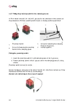
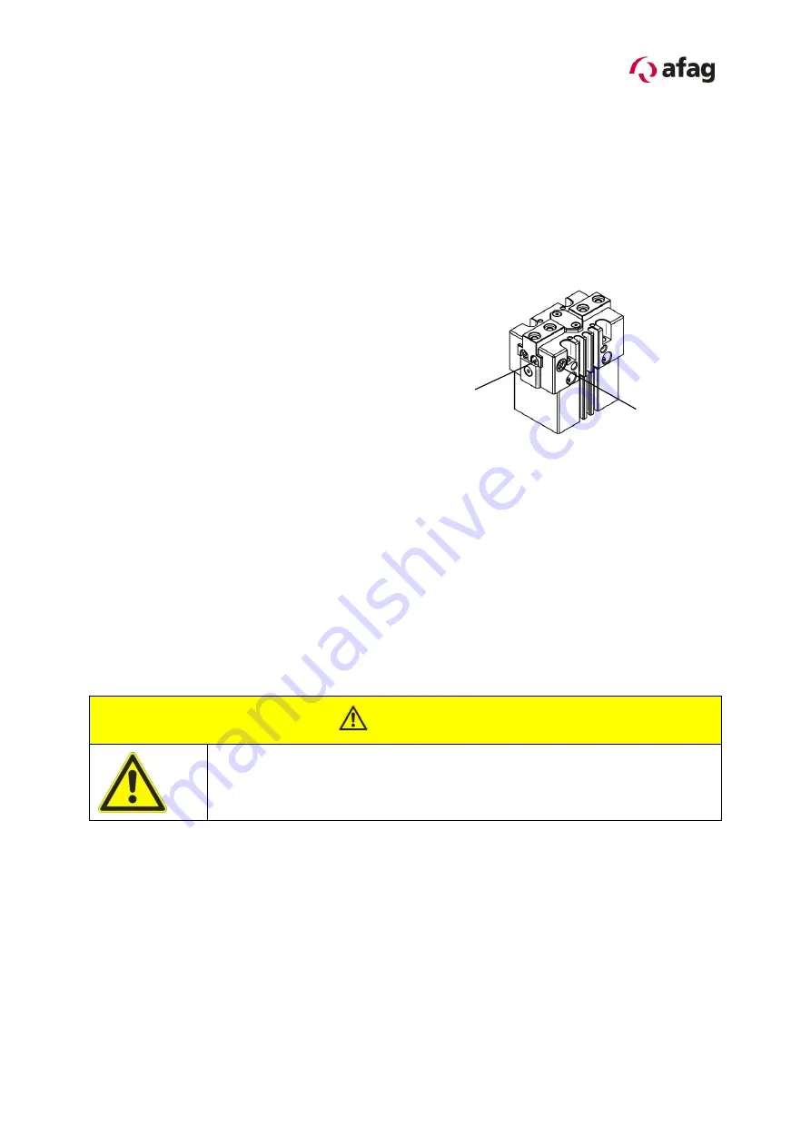
Setting the Inductive Sensors
Remove the cover (1)
Loosen the fastening screw under the
cover (slot-head screwdriver, size 00)
Adjust the set screws for stroke
detection (2)
Check the sensor for proper
functioning and readjust, if necessary
Retighten the fastening screw
Reinstall the cover
3.2.6 Start-up of the UG Universal gripper
Aerate the total system slowly.
Pay attention to the permissible values (technical data) regarding:
-
load capacity
-
motion frequency
-
moment loads on the guide system
CAUTION
Limbs may be squeezed by moving components.
Make sure that there are no persons or tools within the operating range of the
module.
Carry out a test run
-
at first at slow traverse speed,
-
afterwards under operating conditions.
1
2
Summary of Contents for 50030771
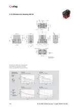
Page 14: ...14 UG 20 UG 25 OI vers 3 2 gb 06 08 14 doc 3 1 8 Dimensions drawing UG 20 ...
Page 15: ...UG 20 UG 25 OI vers 3 2 gb 06 08 14 doc 15 3 1 9 Technical data of the UG 20 ...
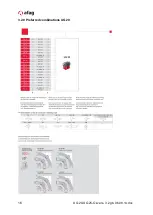
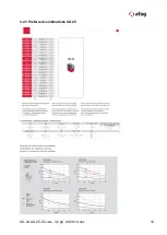
Page 16: ...16 UG 20 UG 25 OI vers 3 2 gb 06 08 14 doc 3 2 0 Preferred combinations UG 20 ...
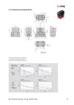
Page 17: ...UG 20 UG 25 OI vers 3 2 gb 06 08 14 doc 17 3 2 1 Dimensions drawing UG 25 ...
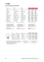
Page 18: ...18 UG 20 UG 25 OI vers 3 2 gb 06 08 14 doc 3 2 2 Technical data of the UG 25 ...
Page 19: ...UG 20 UG 25 OI vers 3 2 gb 06 08 14 doc 19 3 2 3 Preferred combinations UG 25 ...

