Installation, assembly & setting
28 – 56
Assembly instructions EN
SA-3 I SA-3-FL I SA-6 I SA-6-FL
Edition 01/2021
Rev. 4.5
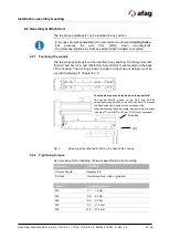
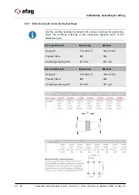
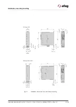
6.2.3 Attachment grid and centering bushings
Use the centring bushings included in the scope of delivery for positioning.
Insert the centering bushings in two diagonally opposite holes of the
attachment grid.
SA-3 und SA-3-FL
Base body
Bracket
Hole grid
30 x 30 mm
30 x 30 mm
Thread / Bore
M4
M4
Centering bushing (H7)
Ø 7 mm
Ø 7 mm
SA-6 und SA-6-FL
Base body
Bracket
Hole grid
48 x 48 mm
30 x 30 mm
Thread / Bore
M6
M4
Centering bushing (H7)
Ø 9 mm
Ø 7 mm
Summary of Contents for 50113773
Page 54: ...54 56 Assembly instructions EN SA 3 I SA 3 FL I SA 6 I SA 6 FL Edition 01 2021 Rev 4 5 ...
Page 55: ...Assembly instructions EN SA 3 I SA 3 FL I SA 6 I SA 6 FL Edition 01 2021 Rev 4 5 55 56 ...
Page 56: ...56 56 Assembly instructions EN SA 3 I SA 3 FL I SA 6 I SA 6 FL Edition 01 2021 Rev 4 5 ...


