Installation, assembly & setting
Assembly instructions EN
SA-3 I SA-3-FL I SA-6 I SA-6-FL
Edition 01/2021
Rev. 4.5
31–56
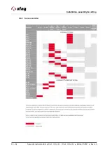
6.3 Motor layout
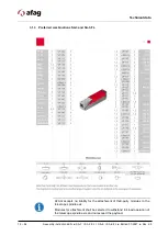
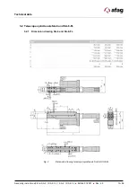
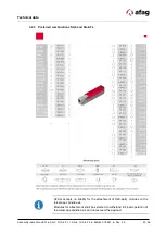
The motor arrangement can be either front, left, right or axial.
Fig. 6
Possible arrangement of the servomotor
6.3.1 Arrangement options
Fig. 7
Mounting the motor RIGHT / AXIAL
1. Base body
6. Coupling housing
2. Bracket
7. Servo motor
3. Linear guide
8. Holding brake
4. Ball screw axis
9. Motor/Encoder connector
5. Toothed belt housing
10. Reference switch connector
10
1
8
4
5
6
7
9
2
3
Motor RIGHT
Motor AXIAL
Summary of Contents for 50113773
Page 54: ...54 56 Assembly instructions EN SA 3 I SA 3 FL I SA 6 I SA 6 FL Edition 01 2021 Rev 4 5 ...
Page 55: ...Assembly instructions EN SA 3 I SA 3 FL I SA 6 I SA 6 FL Edition 01 2021 Rev 4 5 55 56 ...
Page 56: ...56 56 Assembly instructions EN SA 3 I SA 3 FL I SA 6 I SA 6 FL Edition 01 2021 Rev 4 5 ...

