background image


EU-20-OI-v-1.2 gb. 28.07.14.docx


31 

 4.6


Disassembly and repair


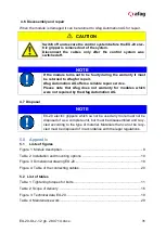
When the module is damaged it can be returned to Afag Automation AG for repair.  


CAUTION


Switch off and secure the control system before the EU-20 elec-
tric gripper is removed out of the system. 
Disconnect  the  cables  only  after  the  control  system  was 
switched off.


NOTE


If the module turns out to be faulty during the warranty it must 
be returned to Afag for repair.  
Afag Automation AG offers a reliable repair service.  
Please  note  that  Afag  does  not  warranty  for  modules  which 
were not repaired by the Afag Automation AG.


4.7  Disposal 

NOTE


EU-20 electric grippers which ca not be used any more must not be 
disposed of as a complete unit, but must be disassembled and recy-
cled according to the type of material. Materials than ca not be recy-
cled must be disposed of in accordance with the legal regulations. 

 
5.0  Appendix 

5.1 

Liste of figures 

Figure 1: Module description ...................................................................................... 8


Table 2: Installation and mounting options ............................................................... 10


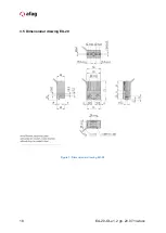
Figure 3: Dimensional drawing EU-20 ...................................................................... 18


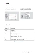
Figure 4: Table of the connecting cables .................................................................. 20


5.2  List of tables 

Table 1: Tightening torques for bolts ........................................................................ 11


Table 2: Scope of delivery ........................................................................................ 16


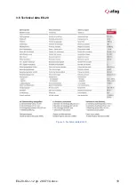
Figure 3: Technical data EU-20 ................................................................................ 19


Table 4: Maintenance work....................................................................................... 29


Summary of Contents for 50346017

Page 1: ...Electric gripper EU 20 Declaration of Incorporation Module Information Montage Instruction Maintenance Instruction Translation of the Original Montage Instructions Copyright by Afag Automation AG ...

Page 2: ...20 OI v 1 2 gb 28 07 14 docx Symbols WARNING Indicates a possible dangerous situation Non compliance with this information can result in death or se rious personal injuries invalidity CAUTION Indicates a possibly dangerous situation Non compliance with this information can result in damage to property or light to medium personal injuries NOTE Indicates general notes useful operator tips and operat...

Page 3: ...Incorporation into a line 12 2 10 Preferred combinations of the EU 20 14 3 0 Montage Instruction 15 3 1 Scope of delivery 16 3 2 Intended use 16 3 3 Warranty 17 3 4 Safety instructions 17 3 5 Dimension drawing 18 3 6 Technical data 19 3 7 Gripper load 20 3 8 Electrical interface 20 3 9 Standard operation 21 3 10 Checking the gripping process with external sensors 23 3 11 Fitting the EU 20 gripper ...

Page 4: ...struction 28 4 1 Maintenance and servicing 28 4 2 Regular maintenance 29 4 3 Further maintenance 29 4 4 Troubleshooting 29 4 5 Accessories 30 4 6 Disassembly and repair 31 4 7 Disposal 31 5 0 Appendix 31 5 1 List of figures 31 5 2 Tabellenverzeichnis 31 ...

Page 5: ... EMV Guideline 2004 108 EG EG Production Safety Directive 2001 95 EG EG RoHS 2002 95 EG The relevant technical documentation is compiled in accordance with part B of Annex VI The relevant technical documentation in accordance with part B of Annex VI will be transmitted in response to a reasonable request by the national authori ties in printed from or in electronic from pdf Increase of the harmoni...

Page 6: ... been declared in conformity with the provisions of this Directive 2006 42 EC where appropriate Name and address of the person authorised to compile the relevant technical docu mentation Lanz Beat PM Marketing Services Afag Automation AG Place Date Huttwil 28 07 2014 Markus Werro Managing Director Afag Automation AG Siegfried Egli Head of HT Afag Automation AG ...

Page 7: ...ndling storage The following conditions must be met for transport and storage Storage temperature 0 50 Humidity 90 non condensing CAUTION The EU 20 electric grippers are packed in the original box In the case of improper handling the module may drop out of the box when it is unpacked and cause injuries to limbs The weight of the EG electric gripper is less than 0 290 kg NOTE Please note A technica...

Page 8: ...ator contains an integrated electronics The electronics control the motor on the basis of the motor current The gripper maintains its force by a spring element he works so very economically and environmentally Note Gripper actuator and gripper pliers must be ordered separately The EU 20 electric gripper consists of the gripper actuator 1 with integrated electric motor The transition piece 2 takes ...

Page 9: ...l Data Please note The length L and the offset X of the gripper fin gers should not exceed the recommended dimensions in the gripping force diagrams of the corresponding pliers Please see centric gripping force diagrams page 3 7 2 7 Mounting Connection WARNING The gripper fingers are moved by the electric control If the gripper fingers cannot move freely there is danger of injuries and bruises nea...

Page 10: ...he control system may cause unintentional movements of the module which may lead to personal injuries 2 8 Installation and fastening possibilities The EU 20 electric gripper can be installed horizontally and vertically Depending on the use and application the grippers can be fastened on the wide side with two M4 bolts in a 30 mm grid You can also fasten the grippers on the rear side with a 4xM3 ad...

Page 11: ...and a di ameter of 4 4 mm VP 149 connecting plate order no 50332010 2 10 Tightening torques for bolts The bolts to be used for assembly must at least satisfy the following conditions Standard VDI 2230 Strength class 8 8 Surface galvanized blue oiled or greased Thread Tightening torques M2 M2 5 M3 0 3 0 35 Nm 0 5 0 73 Nm 1 1 1 4 Nm M4 2 6 3 3 Nm M5 5 2 6 5 Nm M6 9 0 11 3 Nm M8 21 6 27 3 Nm Table 1 ...

Page 12: ... safe operation must be en sured Ensure that the operator cannot reach into the operating range of the EU 20 electric gripper during normal operation Ensure that there is no danger to the operator of the system in special operating modes The concept depends on the safety concept of the system and the attached gripper fingers WARNING Due to the decentral controller the operator of the gripper needs...

Page 13: ...on the design of the gripper jaws there is an addi tional safety risk e g by shearing The EU 20 electric gripper may only be used in accordance with the intended purpose Ensure that the operator cannot reach into the operating range of the EU 20 electric gripper during normal operation This can be achieved by taking appropriate safety measures such as casings a light grid or by disconnecting the d...

Page 14: ...14 EU 20 OI v 1 2 gb 28 07 14 docx 2 12 Preferred combinations of the EU 20 ...

Page 15: ...nto service until the final machinery into which it is to be incorporated has been declared in conformity with the provisions of this Directive 206 42 EG Annex II B IV where appropriate The manufacturer Afag Automation AG Fiechtenstrasse 32 CH 4950 Huttwil Tel 41 62 959 87 02 www afag com Name and address of the person authorised to compile the relevant technical docu mentation Lanz Beat PM Market...

Page 16: ...t a danger to property and the environment Combined with other modules they can be used as a pick place station NOTE Any use that exceeds the use mentioned above is regarded as im proper The manufacturer does not accept any liability for damage resulting from such use The risk is that of the user alone Intended use also includes paying attention to the Montage Instructions and observ ing the maint...

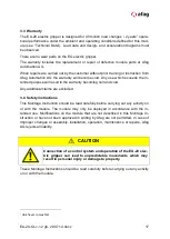
Page 17: ... in the warranty becoming null and void Any additional claims are excluded 3 4 Safety instructions This Montage Instruction should be read carefully before carrying out any activity on or with the module The module may only be deployed in accordance with the in tended use Modifications on the module that are not described in this Montage In struction or have not been approved in writing by Afag ar...

Page 18: ...18 EU 20 OI v 1 2 gb 28 07 14 docx 3 5 Dimensional drawing EU 20 Figure 3 Dimensional drawing EU 20 ...

Page 19: ...EU 20 OI v 1 2 gb 28 07 14 docx 19 3 6 Technical data EU 20 Figure 3 Technical data EU 20 ...

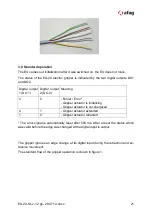
Page 20: ...onnecting cable Strand colour Assignment white 24VDC 1A brown 0 VDC GND yellow Digital input DI Edge change 0 24V extend Edge change 24V 0V retract green Digital output 1 DO 1 1 retracted on resistance grey Digital output 2 DO 2 1 extended Figure 4 Table of the connecting cables ...

Page 21: ... 2 Meaning 0 0 Fehler Error Gripper actuator is initializing Gripper actuator is not energized 0 1 Gripper actuator extended 1 0 Gripper actuator retracted The error signal is automatically reset after 500 ms After a reset the status which was valid before the edge was changed at the digital input is output The gripper ignores an edge change at its digital input during the retraction and ex tensio...

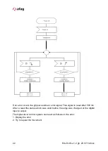
Page 22: ...ends an error signal This signal is reset after 500 ms After a reset the status which was valid before the edge was changed at the digital input is output The higher level control system can react as follows on the error 1 Display the error 2 Try to repeat the movement ...

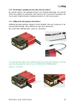
Page 23: ...ect whether the gripper actuator is in the correct position 3 11 Fitting the EU 20 gripper with initiators Additional proximity switches magnetic can be installed in the two C grooves for ab solute position sensing These initiators are part of our accessories INI c10x28 5 Em PNP NO M8x1 Order no 50033432 You also have the option of two inductive sensors to be mounted directly on the tong head must...

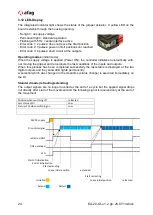
Page 24: ...ions of the inputs and outputs When this process has been completed successfully the last status is displayed at the two digital outputs and the yellow LED lights permanently A potential which was changed in the meantime status change is executed immediately on the DI Standard mode retracting extending The output signals are no longer inverted at the end of a cycle but the applied signal drops out...

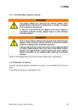
Page 25: ...f the EU 20 electric gripper needs not to be near the product so that third persons might be endangered by the gripper operation Always switch off the control and protect it from being switched on again unintentionally when you work on the EU 20 electric gripper The signals of the control system may cause uninten tional movements of the module which may lead to personal injuries Observe the Montag...

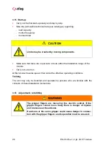
Page 26: ...Carry out a test run At first at slow traverse speed then under the effective operating conditions Training The unit may only be installed and operated by persons who are familiar with the contents of these Installation Instructions 3 16 Adjustment retrofitting WARNING The gripper fingers are moved by the electric control If the gripper fingers cannot move freely there is danger of injuries and br...

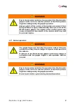
Page 27: ...intentional movements of the module which may lead to personal injuries 3 17 Normal operation WARNING The gripper fingers are moved by the electric control If the jaws cannot move freely there is danger of injuries and bruises near the add ons If add ons at the EU 20 electric gripper could cause danger in connection with the gripper fingers a safe operation must be ensured WARNING Due to the decen...

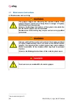
Page 28: ...U 20 electric gripper was incorporated Maintenance and servicing may only be carried out by qualified personnel WARNING Always switch off the control and protect it from being switched on again unintentionally when you work on the EU 20 electric gripper The signals of the control system may cause uninten tional movements of the module which may lead to personal injuries Observe the Montage Instruc...

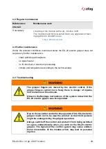
Page 29: ... technical data 4 4 Troubleshooting WARNING The gripper fingers are moved by the electric control If the gripper fingers cannot move freely there is danger of injuries and bruises near the add ons Observe the Montage Instructions of the system into which the EU 20 electric gripper was incorporated WARNING Due to the decentral controller the operator of the EU 20 electric gripper needs not to be ne...

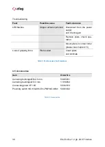
Page 30: ...rs check ope ration Mount pliers in correct order please see chapter 2 5 Loss of gripping force Pliers soiled Clean pliers and lubricate Table 5 Faults causes fault clearance 4 5 Accessories Item Order No Centering bushings Ø5x2 5 mm Centering bushings Ø7x3 mm Connecting plate VP 149 Proximity switch INI c10x28 5 Em PNP NO M8x1 50035831 11016850 50332010 50033432 Table 6 Accessories ...

Page 31: ...oes not warranty for modules which were not repaired by the Afag Automation AG 4 7 Disposal NOTE EU 20 electric grippers which ca not be used any more must not be disposed of as a complete unit but must be disassembled and recy cled according to the type of material Materials than ca not be recy cled must be disposed of in accordance with the legal regulations 5 0 Appendix 5 1 Liste of figures Fig...

Page 32: ...32 EU 20 OI v 1 2 gb 28 07 14 docx Afag Automation AG Fiechtenstrasse 32 4950 Huttwil Switzerland Tel 41 62 959 86 86 Fax 41 62 959 87 87 e mail sales afag com Internet www afag com ...

Reviews: